3. From the File menu, select Scan Product and check that the correct product version is displayed.
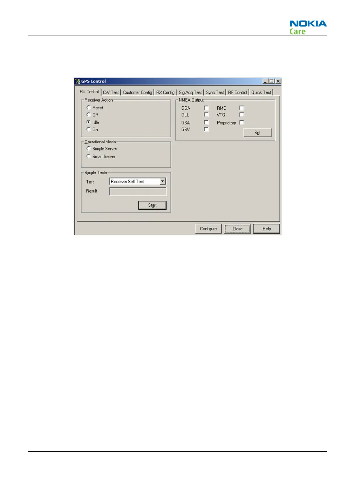
4. From the Testing menu, select GPS Control. This opens up
GPS Control
dialogue box, as shown in the
figure below, and enables the GPS.
Figure 23 GPS Control dialogue box
Select Idle to confirm the GPS is enabled and is in idle mode; at this point all clocks should be present,
GPS_En_Reset & SleepX should be high, and Vdd_Dig, Vcc_TCXO & Vcc_PLL/VCO will be present.
Receiver On turns on all RF sections of the ASIC and so all LDOs will be on.
Quick Test window
This test will perform 3 tests in one: Self test, Oscillator Test and CW Test and will provide a Pass/Fail Response
for each. The HW Self Test confirms basic communication with the GPS ASIC. The oscillator test confirms the
frequency accuracy of the GPS TCXO against the Ref_Clk. The CW Test confirms end-to-end connectivity
between the GPS antenna pogo pins and the GPS ASIC. It also contains a receive button.
Before this test is performed a known good phone should be tested in order to calibrate the setup. The signal
level of the Signal Generator should be adjusted so a reading of SNR 40 dB is achieved with the reference
unit. A good starting point is to set up the signal generator to -45dBm.
These checks are part of GPS failure troubleshooting (page 3–63).
RM-484; RM-485; RM-486
BB Troubleshooting
Issue 1 COMPANY CONFIDENTIAL Page 3 –61
Copyright © 2009 Nokia. All rights reserved.