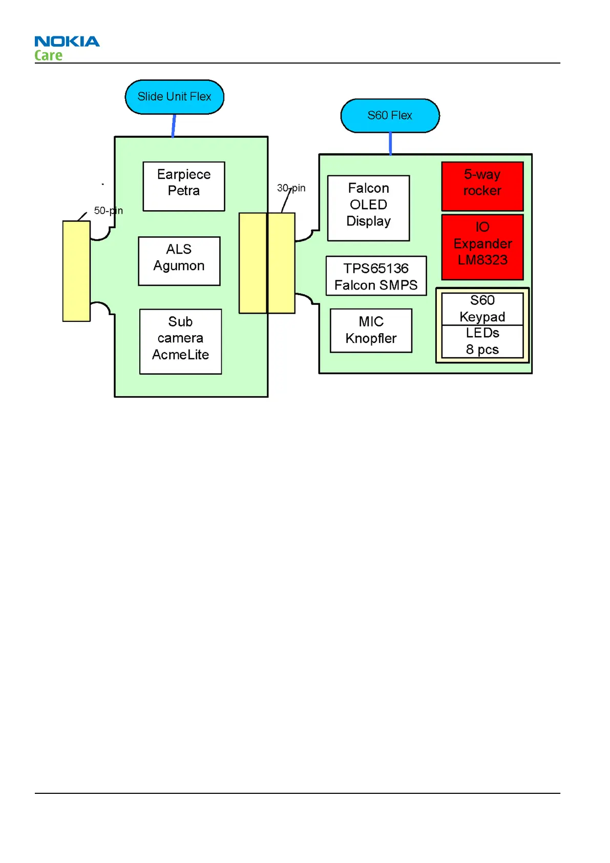
Figure 71 UI/slide module partition
Display module
Display features
•
2.6” AM OLED QVGA display (240 columns x 320 rows) supports up to 16.7M colors
•
Ambient Light Sensor to optimize display brightness and power consumption
Display interface
Figure
Display interface block diagram
below shows how the display related signals are routed. Hurricane
display HWA controlling is done via LoSSI bus and pixel data is transferred via ViSSI-12 bus. MeSSI-8 is the
interface between Hurricane display HWA and Falcon OLED display.
As Falcon is self-emissive AM OLED display, no LED driver based backlighting is needed. An external DC-DC
convertor TPS65136 is used for the display powering.
Supply voltages for Falcon display:
1 VIO from the baseband SMPS (1.8V )
2 VBAT from Battery(3.7V)
3 ELVDD supply from external DC/DC converter TPS65136 (+4.6V)
4 ELVSS supply from external DC/DC converter TPS65136 (-4.9V)
EL_ON signal from Falcon display is enable for the DC/DC converter TPS65136.
RM-484; RM-485; RM-486
System Module and User Interface
Page 8 –20 COMPANY CONFIDENTIAL Issue 1
Copyright © 2009 Nokia. All rights reserved.