3 Options
BU 0600 en-2319 61
3.3 Frequency addition and subtraction via control boxes
If the parameter P549 (PotentiometerBox Function) is set to 4 “Frequency addition” or 5 “Frequency
subtraction”, a value can be added
or subtracted using the value keys of the ControlBox or
the ParameterBox.
If the ENTER key
is pressed, the value is saved in P113. The next time the device is started, the
value will be added or subtracted immediately.
As soon as the inverter is enabled, the ControlBox switches to the operating display. Parameterisation
is then no longer possible. Enabling via the ControlBox or ParameterBox is also no longer possible in
this mode, even if P509 = 0 and P510=0.
3.4 Connection of multiple devices to one parametrisation tool
In principle it is possible to access several frequency inverters via the ParameterBox (SK PAR-3X) or
the NORDCON software. In the following example, communication is made via the parameterisation
tool, by tunnelling the protocols of the individual devices (max. 8) via the common CAN system bus.
The following points must be noted:
1. Physical bus structure Establish a CAN connection (system bus) between the devices.
2. Supply the CAN-Bus with power (24 V).
3. Parameterisation
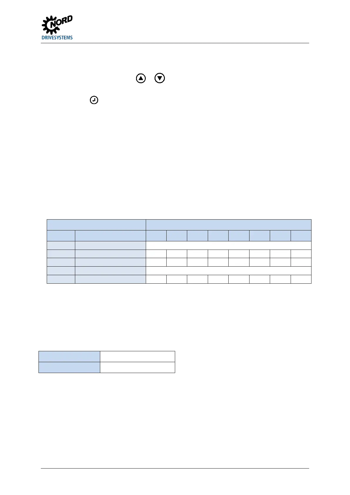
Parameters Settings on the FI
No. Designation FI 1 FI 2 FI 3 FI 4 FI 5 FI 6 FI 7 FI 8
P512 USS address 0 0 0 0 0 0 0 0
P514 CAN baud rate 5 (250 kBaud)
To adopt the addresses, the 24 V supply of the CAN bus must be completely switched off
for approx. 30 sec.
4. Connect the parameterisation tool as usual via RS485 (Terminal: X14 type: RJ12) to the first
frequency inverter.
Conditions / Restrictions:
a. The parameterisation tools must also correspond to the actual software status:
NORDCON
ParameterBox
≥ 4.6 R2
 Loading...


