Hardware description
IF Boot/Reset
Debug out
Interface
MCU
IF MCU USB Analog switch
Battery
External
supply
Power supply
circuitry
Power switch
Analog switch
nRF only
mode switch
Current
measurement
nRf power
source switch
Li-ion
nRF5340
Debug in
Osc
32.768 kHZ
Matching
network
Osc
16 MHz
nRF-USB
External
memory
Buttons
LEDs
GPIO
RF connector
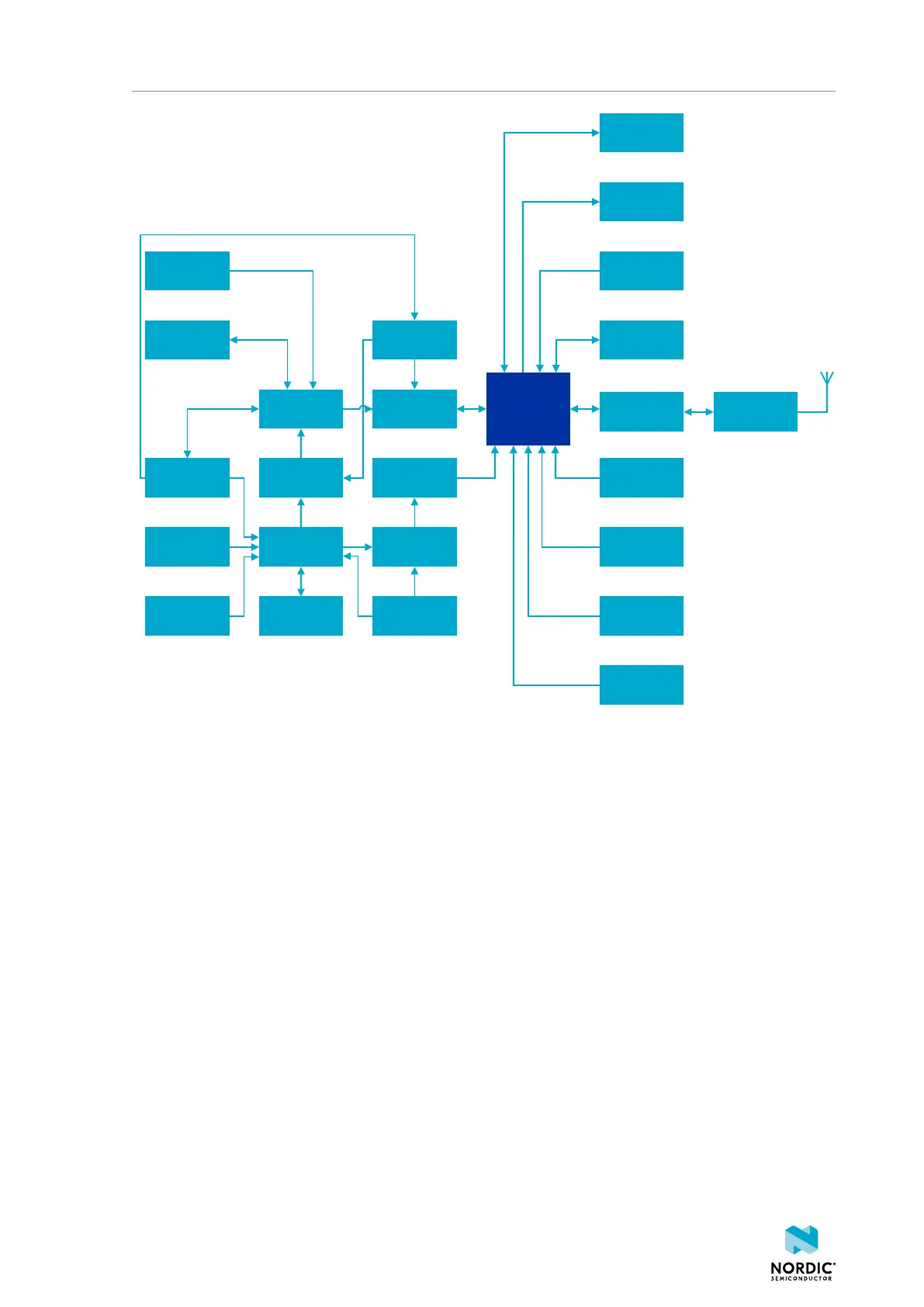
Figure 5: Block diagram
4.3 Power supply
The nRF5340 DK has multiple power options.
The power options are the following:
• USB connector J2 for the interface MCU (5 V)
• USB connector J3 for the nRF5340 SoC (5 V)
• Li-Poly battery connectors J6 or P27 (2.5 V to 5.0 V)
• VIN 3–5V pin on P20 (3.0 V to 5.0 V)
• External supply on P21 (1.7 V to 3.6 V)
• Coin cell battery
4406_638
12

 Loading...
