Hardware description
USB_DETECT
R51
1M0
Q5A
PMCPB5530
Q5B
PMCPB5530
VBUS
R52
150k
SB31
VDD
R50
47k
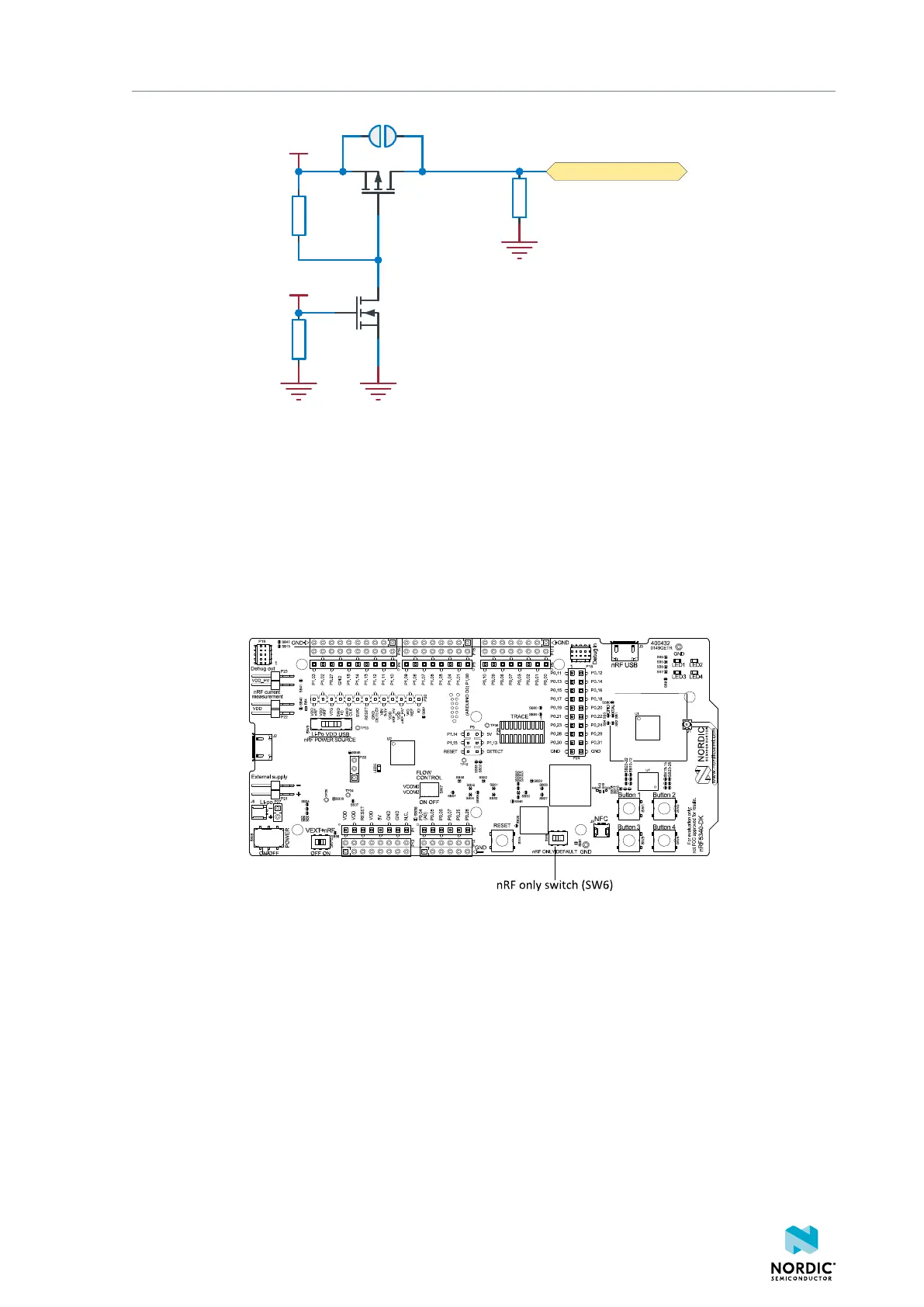
Figure 15: USB detect
4.4.2 nRF only mode
The nRF only mode disconnects the power supply, external memory, and LEDs of the interface MCU. It also
disconnects the signal lines between the nRF5340 SoC and the interface MCU using analog switches.
This is done to isolate the chip on the DK as much as possible and can be of use when measuring currents
on low-power applications.
The power supply of the external memory can be changed to maintain operation in the nRF only mode.
See External memory on page 21.
Figure 16: nRF ONLY switch (SW6)
4.4.3 Signal switches
On the nRF5340 DK, there are multiple analog switches that are used to connect and disconnect signals
based on different scenarios.
4406_638
19

 Loading...
