3
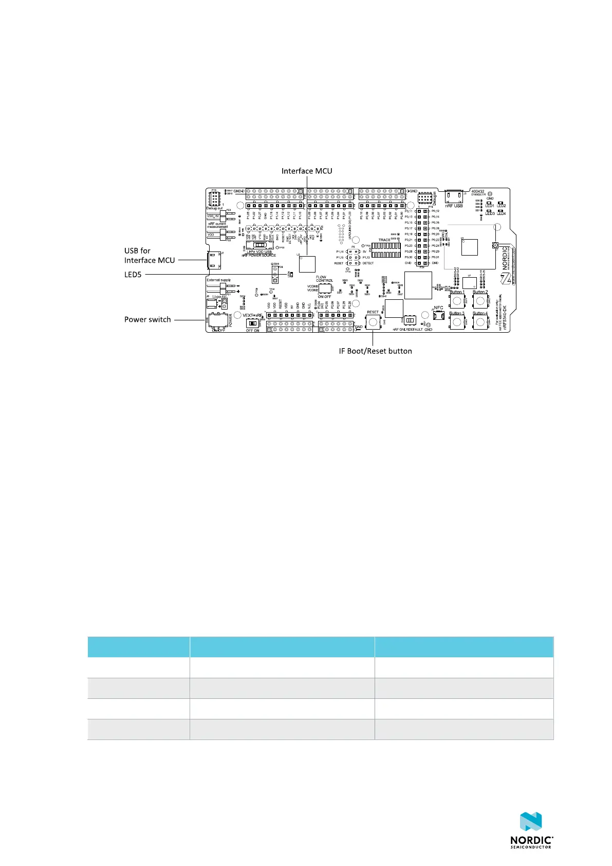
Interface MCU
The interface MCU on the nRF5340 DK runs SEGGER J-Link Onboard (OB) interface firmware. It is used to
program and debug the application firmware of the nRF5340 SoC.
Figure 2: Interface MCU
3.1 Reset button
Reset button (SW5) is connected to the interface MCU on the Development Kit (DK) and resets the
nRF5340 SoC or any device connected to the external programming connectors.
3.2 Virtual serial ports
The interface MCU features two virtual serial ports, each with a UART interface.
The serial ports have the following features:
• Flexible baud rate setting up to 1 Mbps (baud rate 921 600 bps is not supported)
• Dynamic Hardware Flow Control (HWFC)
• Tri-stated UART lines when no terminal is connected
The following table lists the nRF5340 SoC UART GPIO pins and their signals.
Signal nRF5340 UART_0 - Serial Port 0 nRF5340 UART_1 - Serial Port 1
RTS P0.11/TRACEDATA0 P0.19
TXD P1.01 P0.20
CTS P0.10/TRACEDATA1 P0.21
RXD P1.00 P0.22
Table 1: nRF5340 GPIOs mapped to serial port/UART signals
4406_638
8

 Loading...
