Hardware description
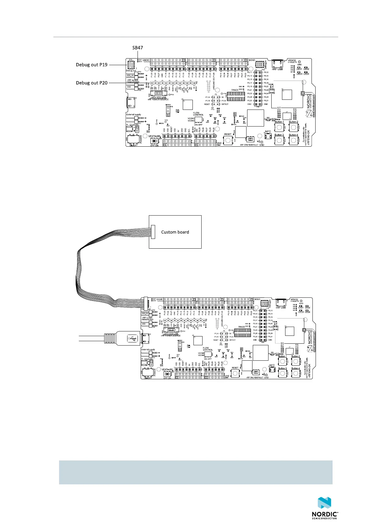
Figure 27: Debug output connectors
4.10.1 Programming an external board
For boards with a standard 10-pin Serial Wire Debug (SWD) connector, or a connector that supports a
standard 10-pin flat cable, it is recommended to connect to P19.
Connect the boards as shown in the following figure.
Figure 28: Connecting an external board to P19
It is recommended to power the external board separately from the DK. The voltage on the external board
must match that of the DK. When the DK is powered through the USB connector, the voltage is 3V.
When pin 3 (SWD0_SELECT) of P19 is connected to GND through the 10-pin flat cable, the interface
MCU programs or debugs the target chip on the external board instead of the onboard nRF5340 SoC.
If it is inconvenient to have a separate power supply on the external board, the nRF5340 DK can supply
power through the Debug out connector P19. To enable this, short solder bridge SB47.
CAUTION: To avoid damaging your board, do not connect a separate power supply to the external
board when SB47 is shorted.
4406_638
28

 Loading...
