5
Current measurement
The current drawn by the application nRF5340 SoC can be monitored on the nRF5340 DK.
Current can be measured using any of the following test instruments:
• Oscilloscope
• Ampere meter
• Power Profiler Kit II (PPK2)
• Power analyzer
See the following chapter for important information on the DK measurement setup. If the PPK2 will be
used for measuring current, see the Power Profiler Kit II User Guide for additional instructions. Power
analyzer measurements are not described in this document.
The application nRF5340 SoC has two possible power supplies: VDD (1.7 V to 3.6 V) and VDDH (2.5 V to 5.5
V). The nRF5340 DK can measure current on both domains. Only the VDD domain current measurement
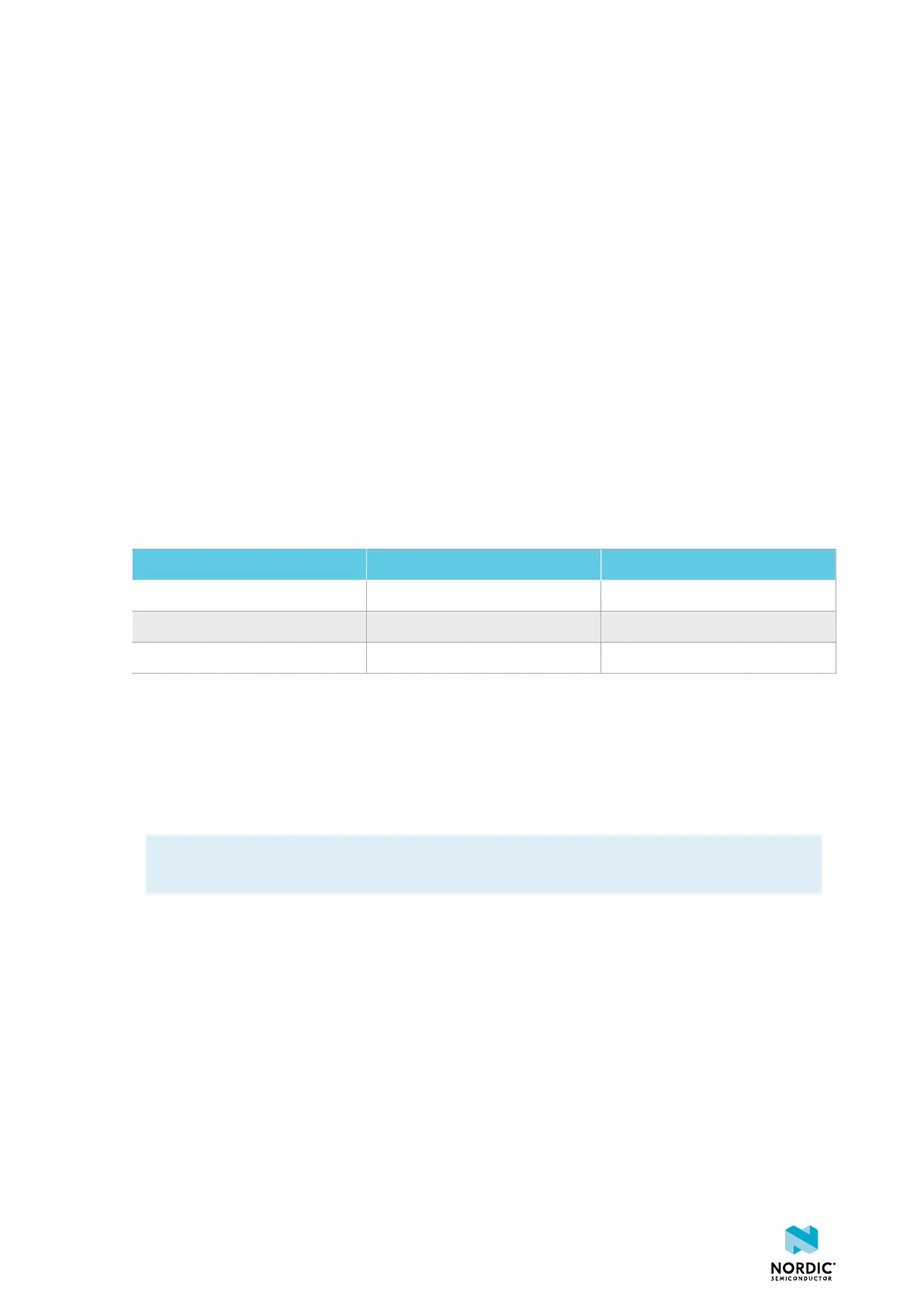
is described here, but the approach is the same with the VDDH supply. See the following table for the
corresponding components.
Component VDD VDDH
Measurement connector P22 P23
Solder bridge SB40 SB41
Series resistor R64 R67
Table 11: Components for current measurement on VDD and VDDH
It is not recommended to use a USB connector to power the DK during current measurements due to
potential noise from the USB power supply. However, when measuring current on an application using the
USB interface of the nRF5340 SoC, USB must be connected. It is recommended to power the DK from a
coin cell battery, external power supply on connector P21 (1.7 V to 3.6 V) or through the Li-Poly connector
J6 or P27 (2.5 V to 5.0 V).
Note: The current measurements are unreliable if a serial terminal is connected to the virtual serial
port.
After programming the nRF5340 SoC, disconnect the USB for the interface MCU.
For more information on current measurement, see the tutorial Current measurement guide:
Introduction.
5.1 Set up the DK
To measure current, you must first prepare the DK.
The suggested configurations split the power domains for the application nRF5340 SoC and the rest of the
DK.
• To put P22 in series with the load, cut the PCB track shorting solder bridge SB40.
• To restore normal kit function after measurement, solder SB40 or apply a jumper on P22.
4406_638
36

 Loading...
