6
RF measurements
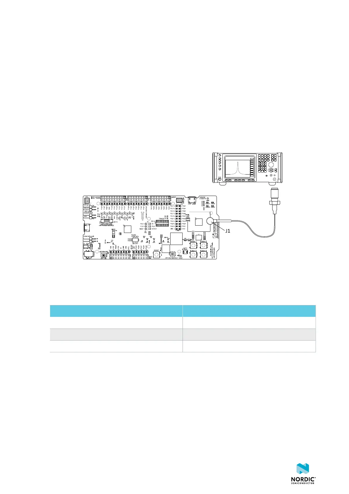
The nRF5340 DK is equipped with a small coaxial connector (J1) for conducting measurements of the RF
signal with a spectrum analyzer.
The connector is of SWF type (Murata part no. MM8130-2600) with an internal switch. By default, when
no cable is attached, the RF signal is routed to the onboard trace antenna.
In this example, a test probe (Murata part no. MXHS83QE3000) is used with a standard SubMiniature
Version A (SMA) connection on the other end for connecting instruments (the test probe is not included
with the kit). When connecting the test probe, the internal switch in the SWF connector disconnects the
onboard antenna and connects the RF signal from the nRF5340 SoC to the test probe.
Figure 38: Connecting a spectrum analyzer
The connector and test probe add loss to the RF signal. See the following table for more information or
consult the test probe user guide if you are using another model.
Frequency (MHz) Loss (dB)
2440 1.0
4880 1.7
7320 2.6
Table 12: Typical loss in connector and test probe, using Murata part no. MXHS83QE3000
4406_638
39

 Loading...
