Hardware description
Power source Power switch bypass Voltage level
Regulator SB34 3.0 V
Coin cell battery SB35 Battery
External supply SB36 1.7 V to 3.6 V
Table 2: Power switch bypass solder bridges
Figure 10: Power switch bypass solder bridges
Note: Connect only one power source at a time. Shorting the solder bridges removes the reverse
voltage protection.
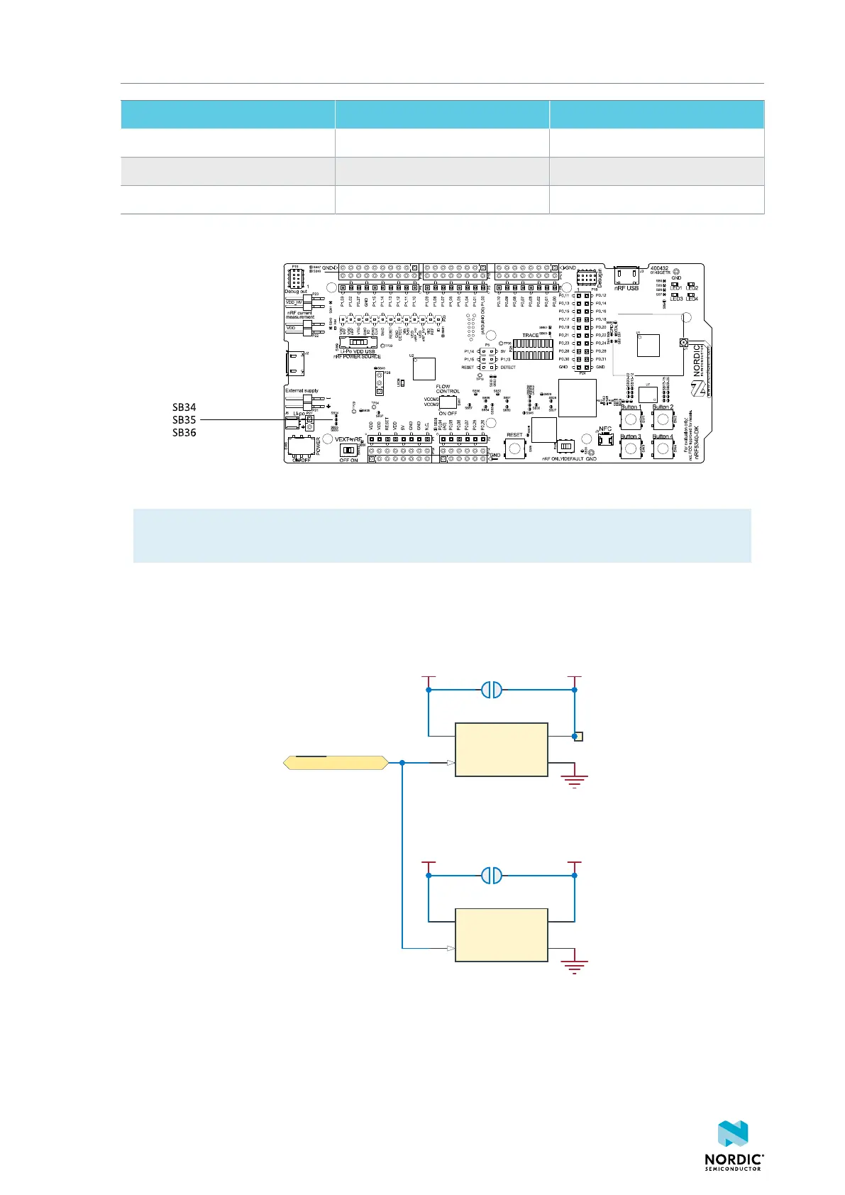
4.3.3 Interface MCU power
The power for the interface MCU is routed through two load switches, one for the VDD supply and one for
the USB supply. This makes it possible to disconnect the interface MCU from the power domain when not
in use.
SB37
VDD_IMCUVDD
SB48
IF_OFF
TP35
VIN
A2
VOUT
A1
CTRL
B2
GND
B1
U19
TCK106AG
VIN
A2
VOUT
A1
CTRL
B2
GND
B1
U22
TCK106AG
VBUS VBUS_IMCU
Figure 11: Interface MCU power switch
These switches are controlled by the presence of a USB connected to the interface MCU USB connector
(J2), and the state of the nRF only switch (SW6). See Modes of operation on page 18 for more
information.
4406_638
16

 Loading...
