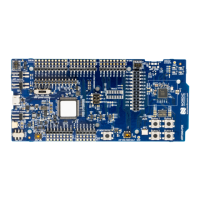
Interface MCU
Note: The serial ports on the nRF5340 DK PCB might be incorrectly labeled. VCOM0 label on the
PCB refers to serial port 0 and VCOM2 refers to serial port 1.
The UART signals are routed directly to the interface MCU. The UART pins connected to the interface
MCU are tri-stated when no terminal is connected to the virtual serial port on the computer. The terminal
software must send a Data Terminal Ready (DTR) signal to configure the UART interface MCU pins.
P0.11/P0.19 (Request to Send (RTS)) and P0.10/P0.21 (Clear to Send (CTS)) can be used for other
purposes when HWFC is disabled on the SoC.
3.2.1 Optional Dynamic hardware flow control
When the interface MCU receives a DTR signal from a terminal, it performs automatic HWFC detection.
HWFC detection
Automatic HWFC detection is done by driving CTS from the interface MCU and evaluating the state of RTS
when the first data is sent or received. If the state of RTS is high, it is assumed HWFC is not in use. If HWFC
is not detected, pins P0.10/P0.21 (CTS) and P0.11/P0.19 (RTS) are free for the nRF application to
use.
After a power-on reset of the interface MCU, all UART lines are tri-stated when no terminal is connected
to the virtual serial port. If HWFC has been used and detected, P0.10/P0.21 (CTS) is driven by the
interface MCU until a power-on reset has been performed or until a new DTR signal is received and the
detection is redone.
Note: When using trace functionality, HFWC on UART_0 must be disabled, see Debug input and
trace on page 26 for more information.
Using HWFC pins for other tasks
To disconnect the pins used by a UART for HWFC, perform the following tasks.
1. Switch SW7 for the selected UART to OFF. This disconnects the line from the interface MCU.
2. Cut the solder bridges for P1.01/P0.20 (TXD) and P1.00/P0.22 (RXD). This ensures they are not
affected by the interface MCU. The lines can be resoldered later if needed.
3.3 Mass Storage Device
The interface MCU features an MSD. This makes the DK appear as an external drive on your computer.
This drive can be used for drag-and-drop programming. However, files cannot be stored on the drive.
When a HEX file is copied to the drive, the interface MCU programs the file to the DK.
The following issues might occur during MSD operation:
• If Windows tries to defragment the MSD, the interface MCU disconnects and becomes unresponsive.
To return to normal operation, power cycle the DK.
• Your antivirus software might try to scan the MSD. Some antivirus programs trigger a false positive
alert in one of the files and quarantine the unit. If this happens, the interface MCU becomes
unresponsive.
• If the computer is set up to boot from USB, it can try to boot from the DK if it is connected. This can
be avoided by unplugging the DK before a computer restart or changing the boot sequence of the
computer.
4406_638
9

 Loading...