Current measurement
• To reprogram the nRF5340 SoC while the DK is prepared for current measurements, remove
measurement devices from P22, and then connect the USB cable.
Figure 35: Preparing the DK for current measurements
5.2 Measure current profile with an oscilloscope
An oscilloscope can be used to measure the average current over a given time interval and capture the
current profile.
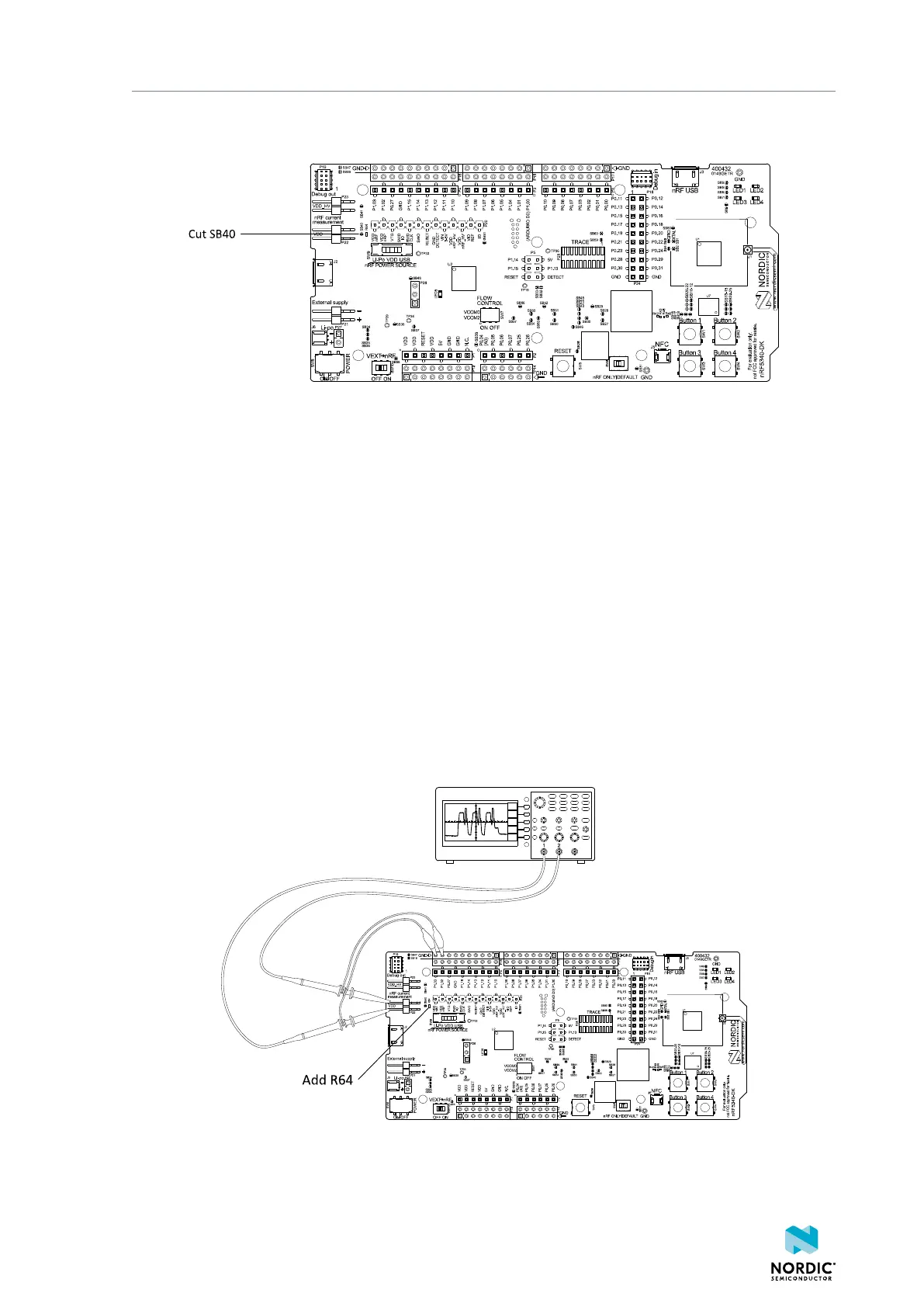
Make sure you have prepared the DK as described in Set up the DK on page 36.
1. Mount a 10 Ω resistor on the footprint for R64.
2. Set the oscilloscope to differential mode or a mode that is similar.
3. Connect the oscilloscope using two probes on the pins of the P22 connector, as shown in the following
figure.
4. Calculate or plot the instantaneous current from the voltage drop across the 10 Ω resistor by taking
the difference of the voltages measured on the two probes. The voltage drop is proportional to the
current. The 10 Ω resistor causes a 10 mV drop for each 1 mA drawn by the circuit being measured.
The plotted voltage drop can be used to calculate the current at a given point in time. The current can
then be averaged or integrated to analyze current and energy consumption over a period.
Figure 36: Current measurement with an oscilloscope
To reduce noise, do the following:
4406_638
37

 Loading...
