Hardware description
TP3
TP2
TP4
TP1
TP5
TP6
TP7
SB54
SB55
SB51
SB53
SB50
SB52
SB57
SB56
NC1
1
IN 1-2
2
NO2
3
COM2
4
NC2
5
GND
6
NO3
7
COM3
8
NC3
9
IN 3-4
10
NO4
11
COM4
12
NC4
13
VCC
14
NO1
15
COM1
16
U5
FSA2466UMX
C42
100nF
VDD
NC1
1
IN 1-2
2
NO2
3
COM2
4
NC2
5
GND
6
NO3
7
COM3
8
NC3
9
IN 3-4
10
NO4
11
COM4
12
NC4
13
VCC
14
NO1
15
COM1
16
U3
FSA2466UMX
NC1
1
IN 1-2
2
NO2
3
COM2
4
NC2
5
GND
6
NO3
7
COM3
8
NC3
9
IN 3-4
10
NO4
11
COM4
12
NC4
13
VCC
14
NO1
15
COM1
16
U6
FSA2466UMX
C41
100nF
C45
100nF
IF_OFF
IF_OFF
IF_OFF
VDD
VDD
TP8
IMCU_BOOT
USB_DETECT
UART2_FC_OFF
VDD
SB46
RESET_PIN
SB45
IMCU_BOOT
SB42
SB43
RESET_PIN
SB44
nRF_ONLY
BOOT/RESET
IF_OFF
R48
4k7
R49
4k7
SHIELD_DETECT
VDD
VDD
IF_OFF
R44
10k
SW6
CAS-220TA
RESET
RESET
RESET
SWDCLK
SWDIO
P0.11/TRACEDATA0
SWD3_RESET
SWD3_SWO
VCOM2_CTS
VCOM2_RTS
VCOM2_RxD
VCOM2_TxD
P1.03
P1.02
UART_1_CTS
UART_1_RTS
UART_1_RxD
UART_1_TxD
TP54
TP57
TP56
TP55
SB28
SB30
SB27
SB29
NC1
1
IN 1-2
2
NO2
3
COM2
4
NC2
5
GND
6
NO3
7
COM3
8
NC3
9
IN 3-4
10
NO4
11
COM4
12
NC4
13
VCC
14
NO1
15
COM1
16
U25
FSA2466UMX
C24
100nF
VDD
IF_OFF
UART_2_CTS
UART_2_RTS
UART_2_RxD
UART_2_TxD
VCOM0_CTS
VCOM0_RTS
VCOM0_RxD
VCOM0_TxD
SWD3_IO
SWD3_CLK
UART1_FC_OFF
IF_OFF
SW7A
Switch
IF_OFF
SW7B
Switch
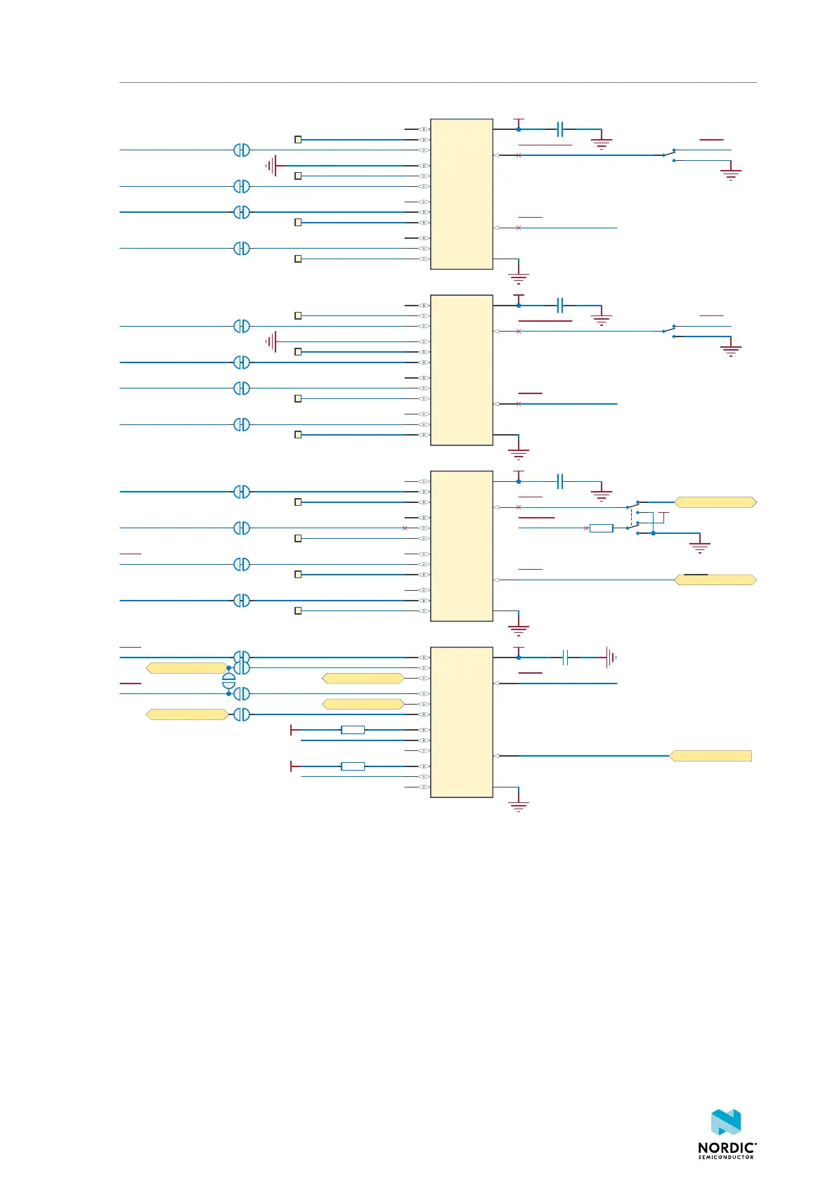
Figure 17: Signal switches
The USB and SW6 control the signal switches by using USB_DETECT as an input to SW6. The interface MCU
can be disconnected either by unplugging the USB cable from J2 or by toggling the nRF ONLY switch SW6.
The signal controls a set of switches (U3, U5, U6) that break the connection between the nRF5340 SoC and
the interface MCU, and control the power for the interface MCU. For more information, see Interface MCU
power on page 16.
Switches U3 and U5 break the connection of the UART lines and SWD/RESET lines. Depending on user
preference, the signal controls the routing of the RESET signal when the interface MCU is connected/
disconnected, as follows:
• When the interface MCU is connected, shorting SB46 connects the RESET pin in the Arduino interface
to the BOOT input of the interface MCU.
• Shorting SB43 connects the RESET pin in the Arduino interface to the RESET button.
4406_638
20

 Loading...
