Hardware description
Part GPIO Solder bridge
Button 1 P0.23 -
Button 2 P0.24 -
Button 3 P0.08 -
Button 4 P0.09 -
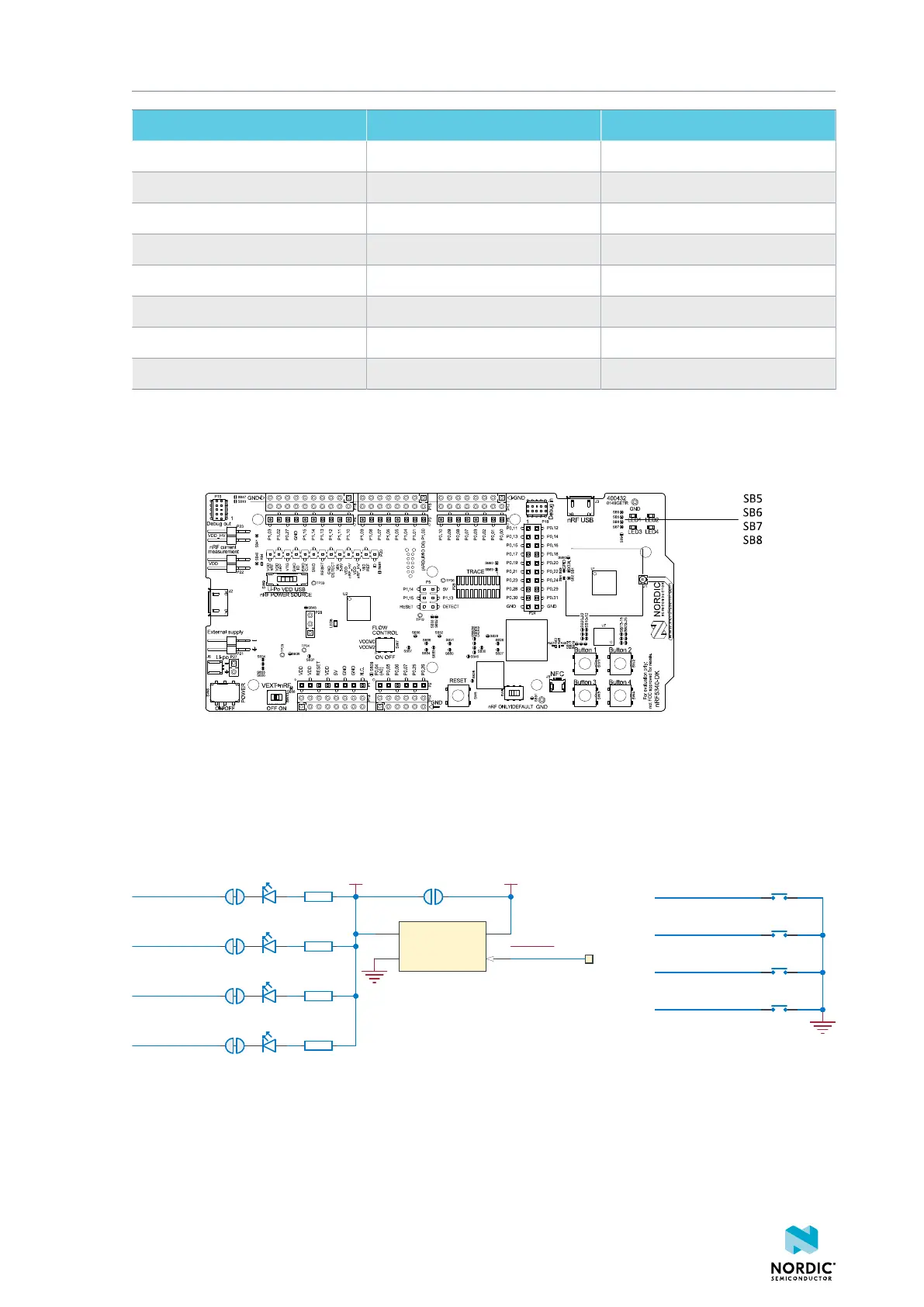
LED 1 P0.28 SB5
LED 2 P0.29 SB6
LED 3 P0.30 SB7
LED 4 P0.31 SB8
Table 6: Button and LED connections
If P0.28–P0.31 are needed elsewhere, the LEDs can be disconnected by cutting the short on SB5–SB8.
See the following figure for more information.
Figure 22: Disconnecting the LEDs
The buttons are active low, which means that input is connected to ground when the button is activated.
The buttons do not have an external pull-up resistor, so the P0.08, P0.09, P0.23, P0.24 pins must be
configured as input with an internal pull-up resistor to use the buttons.
The LEDs are active low, meaning that writing a logical zero (0) to the output pin turns on the LED.
SW1
PB SW
SW2
PB SW
SW3
PB SW
SW4
PB SW
P0.23
P0.24
P0.08/TRACEDATA3
P0.09/TRACEDATA2
R3
220R
R2
220R
SB6
VDD_PER
R4
220R
SB7
R5
220R
SB8
SB5
LED1
L0603G
LED2
L0603G
LED3
L0603G
LED4
L0603G
SB9
VDD
nRF_ONLY
TP22
P0.28/AIN7
P0.30
P0.31
P0.29
VIN
A2
VOUT
A1
CTRL
B2
GND
B1
U4
TCK106AG
Figure 23: Button and LED configuration
4406_638
25

 Loading...
