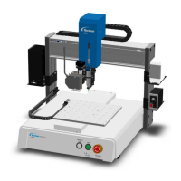
E Series Automated Dispensing System
86 www.nordsonefd.com info@nordsonefd.com 800-556-3484 Sales and service of Nordson EFD dispensing systems are available worldwide.
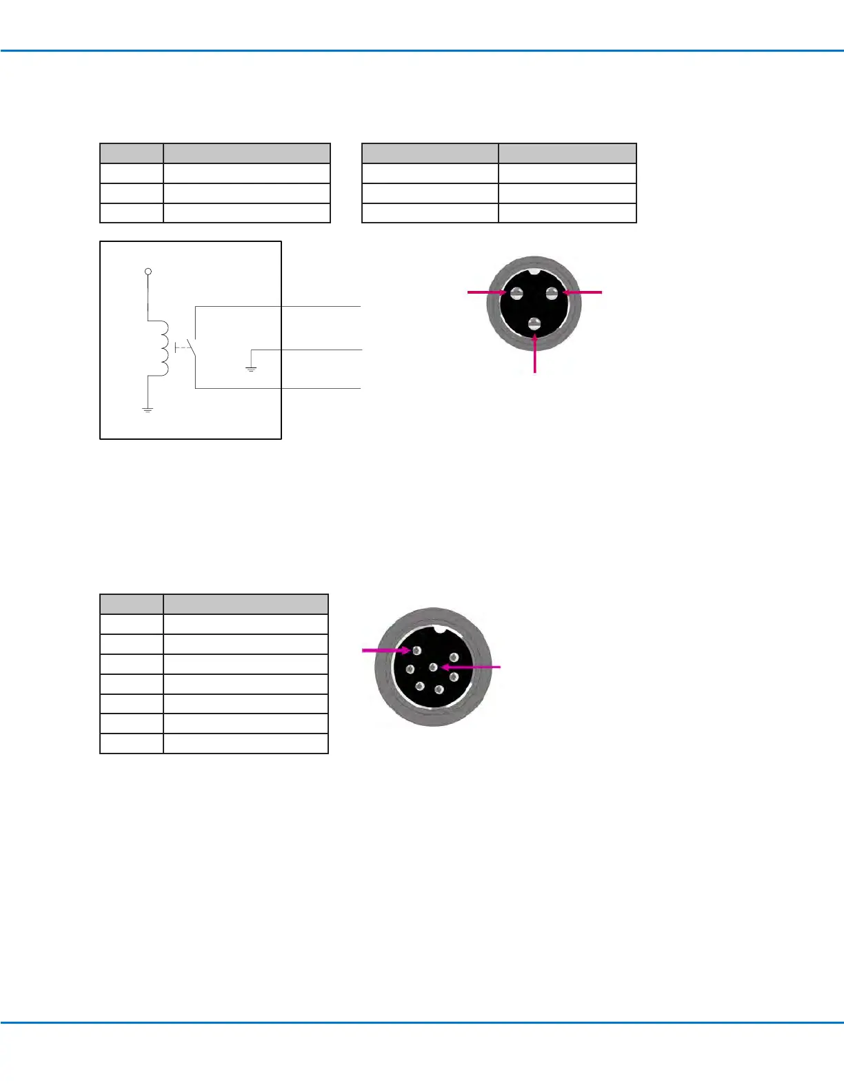
Maximum Voltage Maximum Current
125 VAC 15A
250 VAC 10A
28 VDC 8A
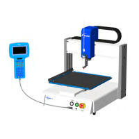
Pin Description
1 NOM (Normally open)
2 COM (Common)
3 EARTH (Ground)
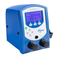
Ext. Control Port
NOTES:
• Inputs are not polarity-sensitive.
• The optional start / stop box accessory facilitates input / output connections to this port. Refer to “Accessories”
on page78 for part numbers.
Pin Description
1 Ground
2 Start signal
3 Motor power
4 Motion idle
5 Run / Teach
6 Emergency stop
7 Emergency stop
1
7
2
1 3
Pin 1
Pin 2
Pin 3
+24V
Relay
Wiring Diagrams
Dispenser Port