Do you have a question about the Nordson EFD PROPlus Series and is the answer not in the manual?
Warning about the risk of electric shock and safety precautions.
Caution regarding maximum allowable air input pressure for equipment.
Instruction to release pressure before servicing pressurized systems.
Warning about hot surfaces and protective measures.
Hazards associated with using halogenated hydrocarbon solvents with aluminum components.
Extreme hazards of high-pressure fluids and injury precautions.
Ensuring equipment is operated and serviced by trained and capable personnel.
Describes intended uses and examples of unintended uses of the equipment.
Ensuring equipment is rated and approved for the operating environment.
Essential instructions to prevent injury during operation and servicing.
Precautions to prevent fire or explosion during operation.
Recommended checks for maintaining continuous trouble-free use of the product.
Safety guidelines for the use and disposal of disposable components.
Steps to take when a system or equipment malfunctions.
Safety information specific to Nordson EFD automated dispensing systems.
Guidelines for selecting an appropriate and safe installation location.
Instructions for connecting the robot and accessories to a power source.
Safety precautions during operation and service procedures.
Safety awareness and operational guidelines for laser systems.
Physical dimensions of the robot models.
China RoHS hazardous material declaration for external electrical connectors.
Information on disposal according to the WEEE Directive.
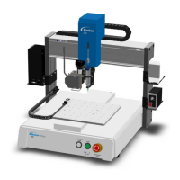
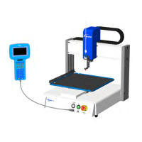
Identifies the main components of the automated dispensing system through a diagram.
Description and labeling of the front panel controls and indicators.
Description and labeling of the back panel ports and connections.
Step-by-step guide for safely unpacking the robot and system components.
Guides on positioning the robot and installing/connecting system components.
Ensures correct installation by verifying tip position relative to camera and laser.
Template showing mounting hole specifications for PRO4 robot fixture plates.
Template showing mounting hole specifications for PROPlus4 robot fixture plates.
Guides on connecting input/output wiring to the robot's I/O port.
Template showing mounting hole specifications for PRO3 robot fixture plates.
Template showing mounting hole specifications for PROPlus3 robot fixture plates.
Defines programs as command files and describes command types.
Provides examples of dispense commands like Dispense Dot, Line Start/End, and Arc Point.
Recommendations for structuring dispense programs effectively.
Explains offsets (camera-tip, laser-tip, tip-workpiece) crucial for calibration.
Tips for selecting effective mark images for system recognition.
Information on where mark images are stored on the DispenseMotion controller.
Procedure for moving the dispensing tip to specific coordinates using the jog window.
Guides on viewing or changing system settings like speed and acceleration.
Steps to access and modify system parameters.
Ensuring the correct robot model is selected for proper system operation.
Guides through the robot initial setup wizard for calibration and offset settings.
Procedure for setting up the tip detector for non-laser systems.
Procedure for setting the camera-to-tip offset using the robot initial setup wizard.
Procedure for setting a mark for workpiece recognition in the robot initial setup.
Procedure for setting the camera scale for accurate pixel-to-measurement conversion.
Procedure for setting the tip-to-workpiece offset using the robot initial setup wizard.
Tests system setup and calibration for non-laser systems.
Explains how the system reacts to Needle Z Detect and Needle XY Adjust commands.
Basic steps for creating and running a dispense program.
Instructions for adding comments to command address lines in a program.
Detailed procedure for using eight trig marks for maximum accuracy in arrays.
Integrates the created trig marks into a Step & Repeat program for orientation adjustment.
Steps to create two trig marks for use in the Step & Repeat program.
Integrates the two trig marks into a Step & Repeat program for orientation adjustment.
Steps to create horizontal and vertical marks on featureless workpieces.
Details using the Edge Adjust command in conjunction with Find Mark commands.
Procedure for creating a mark image of a segment of a curved line.
Integrates Find Mark, Step & Repeat, and Mark Follow commands for curved line dispensing.
Instructions for using Mark Follow Offset commands for more complex curves.
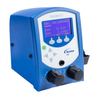
Procedure to open and edit existing PICO files for parameter updates.
Integrates saved PICO Touch Controller settings into a program using a command.
Steps to power on the system, open software, and run a program.
Procedure for executing programs by scanning associated QR codes.
Steps for safely shutting down the DispenseMotion controller and robot.
Details Nordson EFD guarded safety enclosures and their compliance.
Lists and describes pre-configured cables for connecting dispensers and controllers.
Describes the start/stop box for facilitating I/O connections and simulation.
Details the tip detector accessory kit and mounting options.
Describes the lens kit for the high-precision camera.
Details OptiSure AOI software and confocal laser accessory kit for deposit inspection.
Lists various mounting brackets for different valves and dispensers.
Physical dimensions of the robot models.
Dimensions for drilling mounting holes for robot feet.
Illustrates wiring diagrams for the Dispenser Port and Ext. Control Port.
Details the pins and voltage/current ratings for the dispenser port.
Describes pins and notes for the external control port, including start/stop box.
Details pins and schematics for input/output connections.
Schematics showing typical input/output connections to the robot.
Example showing external device power connection to the robot.
Wiring examples for start and emergency stop connections to the external control port.
Controls robot acceleration from point to point or along a continuous path.
Registers current XYZ location as an Arc Point for dispensing along an arched path.
Sets how the dispensing tip raises at the end of line dispensing to control fluid tail.
Causes system to dispense another pattern at a specified location in the program.
Jumps to a subroutine at a specified address and executes commands.
Helps system evaluate marks, especially for irregular patterns.
Evaluates Trig Marks across workpieces in an array without pausing at each mark.
Registers a circle with the center at the current XYZ location.
Used with Circle Run for large circles, defining three points on the circumference.
Adjusts Start Angle and Total Degrees for large circles with Circle 3 Point.
Registers the current XYZ location as a Dispense Dot point.
Sets parameters for how the system dispenses a dot of fluid.
Sets how the dispensing tip raises after dispensing to control fluid tail.
Turns the dispenser OFF or ON at the current address for part of a line.
Registers a point the tip passes through, useful for avoiding obstacles.
Registers current address as end of program, returning tip to home position.
Searches for two fiducial marks to adjust program for orientation changes.
Adjusts program for XY orientation changes using two Fiducial Marks.
Fills a defined area using specified Width and Band parameters.
Searches for a specified mark to adjust program for XY position changes.
Performs robot initialization and moves tip to home position.
Checks for an input signal and turns the input ON or OFF.
Dispenses a stitched series of dots at a specified length and time.
Measures heights on a line path for adjustment by Laser Adjust command.
Sets how the system dispenses a line of fluid, compensating for dispenser delays.
Registers the current XYZ location as a Line Passing point for direction changes.
Searches for a mark and adjusts dispensing path for XY position changes.
Dispenses along a slightly curved line using Find Mark command.
Specifies dispenser for multi-dispenser installations to execute commands.
Performs Needle XY Adjust (camera-to-tip offset) and takes action based on parameters.
Performs Needle Z Detect (tip-to-workpiece offset) and takes action based on parameters.
Implements saved PICO Touch Controller settings from a *.pico file.
Adjusts program for XY orientation changes using Camera Trigger and Trig Mark.
Repeats dispensing pattern onto identical workpieces in rows and columns.
Repeats dispensing pattern onto identical workpieces in Z direction tiers.
Searches for mark images to adjust program for orientation changes in arrays.
Specifies height tip raises after dispense to clear obstacles.
Procedure to teach the camera object size for accurate measurement conversion.
Procedure for setting up the tip detector for non-laser systems.
Sets tip-to-workpiece offset using camera focus and dispense dot.
Details the icons and functions available on the DXF screen.
Sets DXF import preferences such as spline distance, offset, rotate, and mirror.
Steps to convert a DXF file into program commands for dispensing.
Chooses dot pattern order upon import of DXF files with arrays.
Steps to enable the QR code scanning feature in the system.
Associates a QR code with a specific dispense program for execution.
Enables multi-needle dispensing by checking the MULTI NEEDLES option.
Sets camera-to-tip offsets for each dispenser in a multi-dispenser setup.
Inserts Multi Needle commands to specify dispenser use in a program.
Lists and describes input/output configurations and their functions.
Procedure to reconfigure input/output settings using the Expert menu.
| Brand | Nordson EFD |
|---|---|
| Model | PROPlus Series |
| Category | Dispenser |
| Language | English |