Series
3000V
lnput/Output Board
E 1-5.
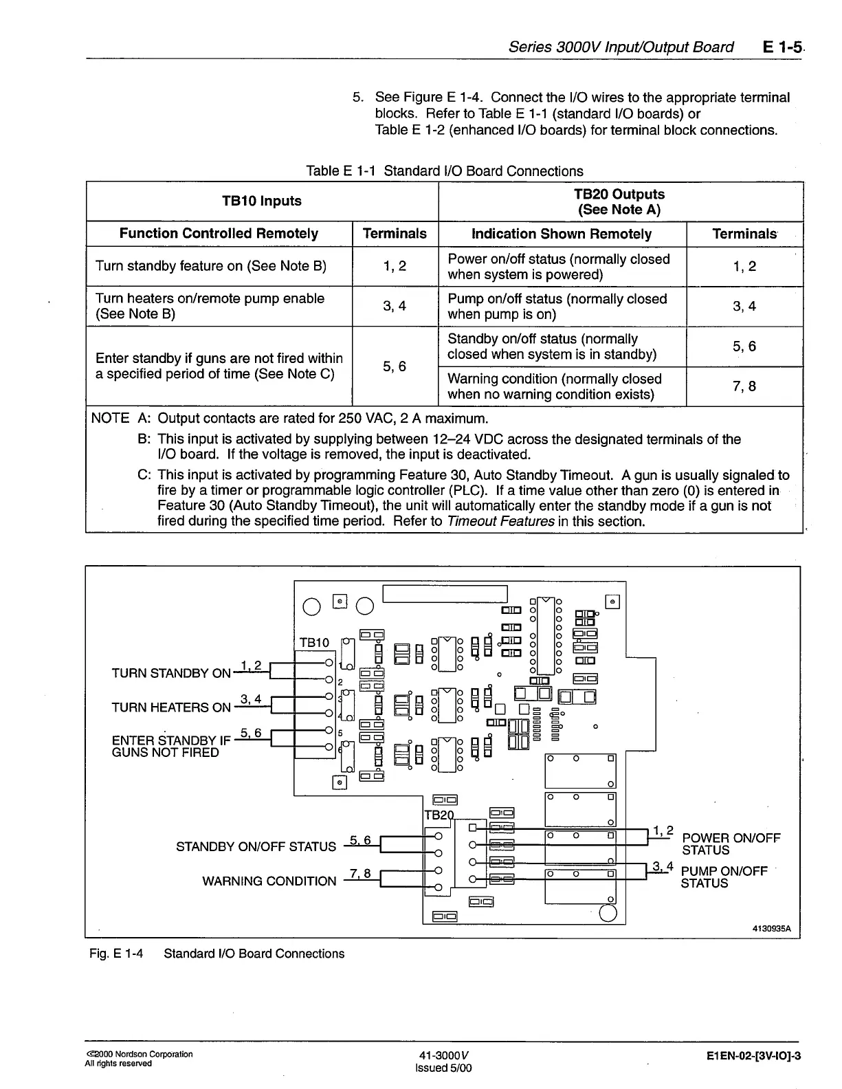
5. See
Figure
E 1-4.
Connect the l/O wires
to the appropriate
terminal
blocks. Refer
to Table E 1-1
(standard
l/O
boards) or
Table E
1-2
(enhanced
l/O
boards) for terminal block connections.
Table E 1-1
Standard l/O Board
Connections
TBl0lnputs
TB20
Outputs
(See
Note A)
Function
Controlled Remotely Terminals
lndication
Shown Remotely
Terminals
Turn standby feature
on
(See
Note B) 1
2
,
Power on/off
status
(normally
closed
when system is
powered)
1 2
t
Turn heaters
on/remote
pump
enable
(See
Note B)
3,4
Pump
on/off status
(normally
closed
when
pump
is
on)
3,4
Enter standby if
guns
are
not fired within
a specified
period
of time
(See
Note
C)
5,6
Standby on/otf status
(normally
closed when
system is in standby)
5,6
Warning
condition
(normally
closed
when no warning
condition exists)
7 8
NOTE A:
Output contacts are
rated
for
250 VAC,2
A maximum.
B:
This input is activated by supplying between 12-24 VDC
across
the
designated
terminals
of the
l/O board. lf the voltage is removed, the input is
deactivated.
C: This input is activated by
programming
Feature
30,
Auto
Standby
Timeout. A
gun
is
usually
signaled to
fire by a timer or
programmable
logic
controller
(PLC).
lf
a
time
value other than zero
(0)
is entered
in
Feature
30
(Auto
Standby
Timeout), the unit will
automatically
enter the standby mode if a
gun
is not
fired during the specified time
period.
Refer
to Timeout Features
in this section.
t-E
t-----tJ
tr
tr
J
lE
El
E--l
E
E
j
lE
EI
EE
tr
E
j
lE
El
HH
EIIg
H
ot
lo
HE
ETE
H
-----b
ol
lo
=ie
ETE
H
-----b
ol
lo
oo
o
tritro
tritr
E]E
tIJ
lard
trII]
t-E
TBlO
tr
2
tr
tritr
EIitr
d.m
E
nrn
METEI
HEE
o
d
E
!
5
f,
TURN STANDBY ON
1 2
TURN HEATERS ON
3
4
ENTER
STANDBY IF
GUNS NOT FIRED
5
1 2
POWER ON/OFF
STATUS
PUMP ON/OFF
STATUS
STANDBY ON/OFF STATUS
4
WARNING CONDITION
4130935A
Fig. E 1-4
Standard l/O Board Connections
@000 Nordson
Corporation
All righls reserved
41-3000v
lssued
5/00
El EN-02-[3V-]OJ-3
 Loading...


