EasyManuals Logo

Nordson MEG II User Manual

Nordson MEG II
49 pages
To Next Page IconTo Next Page
To Previous Page IconTo Previous Page
Page #21 background imageLoading...
Page #21 background image
17
MEG® II Airless Spray Guns with 10 ft Cable
© 2021 Nordson Corporation
1602990-12
3. 
tightened. Insert the upper manifold into the lower manifold. Make sure that the

4. Tighten the stop screw.
5. Thread the manifold lock nut onto the upper manifold and tighten it securely.
6. 
7. 
8. 
manifold.
9. Thread the gun module nut onto the gun module. Tighten the nut to 20-25 ft-lb

10. 
11. Connect the wiring to the terminal block and fuse holder, if used.
7
8
9
10
11
13
12
2
3
4
5
6
14
Wrench Flats
1
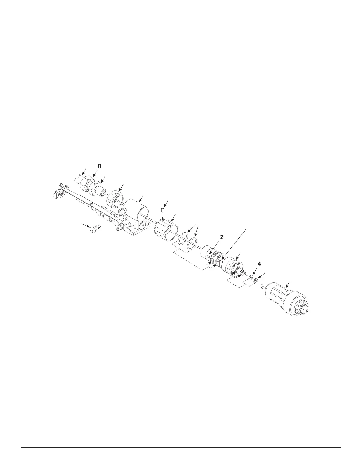
Figure 6 Upper Manifold O-Ring Replacement
1. O-rings
2. Upper manifold groove
3. Upper manifold
4. O-ring
5. O-ring
6. Gun module
7. Electrical conduit
8. Gland nut
9. Connector body
10. Manifold lock nut
11. Lower manifold
12. Gun module nut
13. Set Screw
14. Stop screw

Questions and Answers:

Question and Answer IconNeed help?

Do you have a question about the Nordson MEG II and is the answer not in the manual?

Nordson MEG II Specifications

General IconGeneral
BrandNordson
ModelMEG II
CategoryPaint Sprayer
LanguageEnglish

Related product manuals