Principles of Operation 11
© 2018 Nortek AS
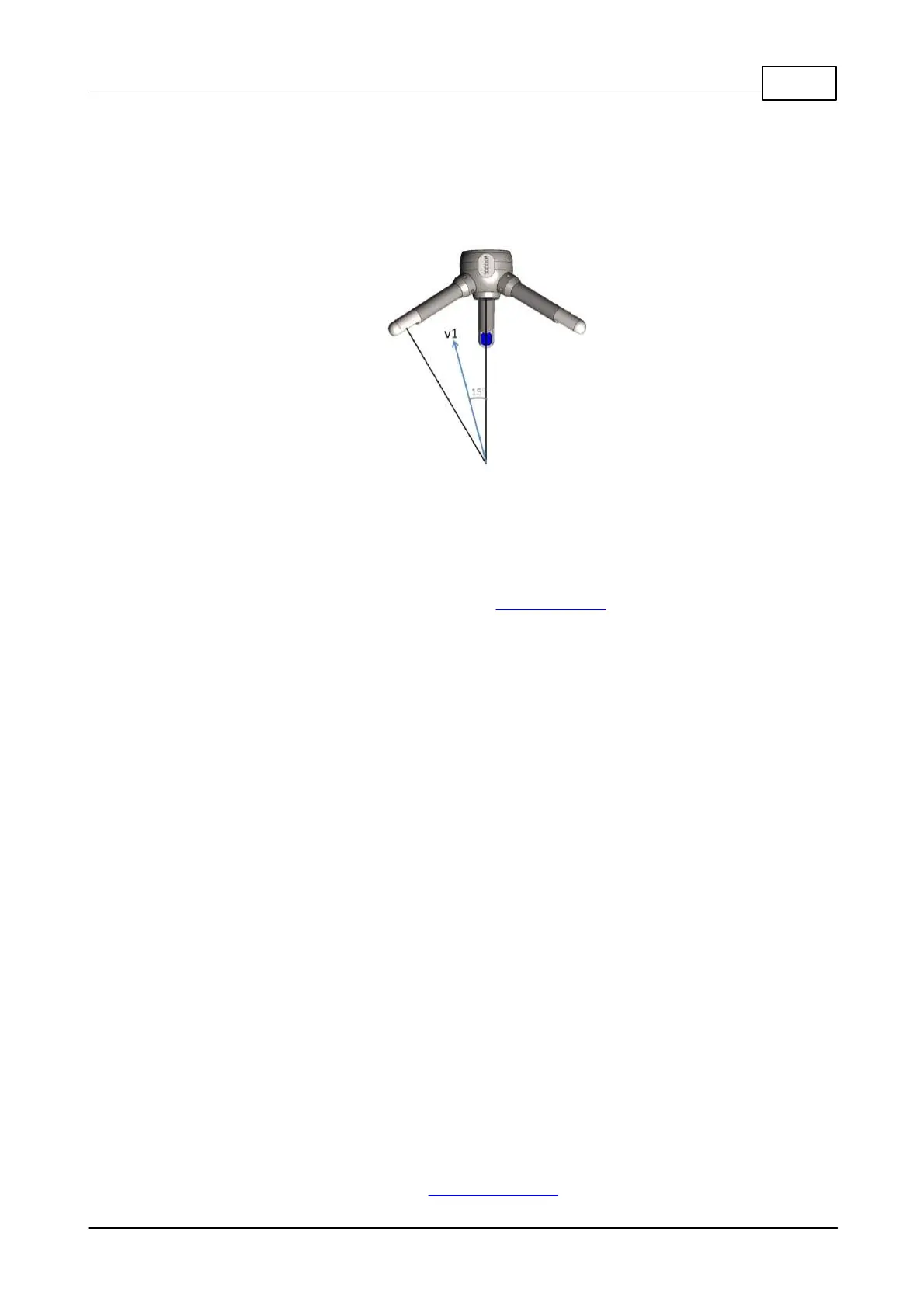
can be considered as proportional to the rate of change along the bisector of the transmit and receive
beams (indicated by the blue arrow in the figure below). Knowing the relative orientation of the
bistatic axes and the receivers makes it easy to calculate 3D velocities. The receive beams are
slanted 30°, thus the angular bisector is 15° away from the transmit beam.
Figure: The transm it/receive beam pair is sensitive to
velocity in the direction of the angular bisector betw een
the beams.
The Z (vertical) and X- and Y (horizontal) velocity limits are tied fundamentally to the geometry and
are not independent. The conversion from beam to XYZ coordinates has Z in the direction that the
central transducer is pointing and XY is always orthogonal to Z. The "Vertical" and "Horizontal"
velocity range is reported in the Deployment planning dialog. The reason that the Vertical range is so
much lower than the Horizontal velocity range is because of the angle used by the passive receivers
(30 degrees). This makes the projection of the passive beams onto the horizontal plane about ~1/4
(sin(15)) (so the maximum horizontal velocity measurable is ~4x the maximum beam velocity) while
the projection of the passive beams onto the vertical plane is 0.96 (cos(15)) (so the maximum vertical
velocity is pretty much the same as the maximum beam velocity). Consequently, the Z-velocity
component yields a lower measurement uncertainty.
In other words, for best measurement, you should always have the largest component of speed in
the horizontal plane from the point of view of the transducers. On another note, even if you do reorient
the probe, when operating at that current, you will likely still have to watch out for wraps in the
velocities if there are any local eddies occur which result in the beam ambiguity velocity being
exceeded.
1.3 Measuring Currents
The processing technique described above is used because the measurement of a phase shift is
more accurate than direct Doppler frequency determinations and provides pulse coherent systems
with their characteristic low noise measurements. The instrument reports the phase shift converted
to an along beam velocity by utilizing the speed of sound in water and the velocity data is output in
m/s.
The user can specify which coordinate system to present the velocity data in. The raw velocity
measurement is a vector in the direction along each of the three or four beams, which is referred to
as beam coordinates. Beam coordinates can be converted to a Cartesian coordinate system (XYZ)
by knowing the beam orientation. Furthermore, the flow can be presented in Earth normal
coordinates (ENU- East, North and Up). In order to get the information referenced to earth
coordinates (ENU - East, North, Up) it is therefore necessary to detect the instrument’s orientation in
space. Attitude sensors, such as magnetometer and tilt are therefore used to aid in the
transformation needed to correct for the instrument’s attitude and motion. The definitions of the
coordinate systems are presented here: Coordinate System
 Loading...


