Comprehensive Manual14
© 2018 Nortek AS
1.5.2 Vectrino
The Vectrino measurement volume is defined as the area where the beams intersect each other. For
the Vectrino that is 5 cm from the transmitter, for the Vectrino field probe, it is 10 cm. The transmit
transducer sends a short pulse that covers 3-15 mm vertically (user adjustable), and the receivers
listen to an echo that corresponds to this volume (see figure below). The diameter of the volume is 6
mm.
The Vectrino side-looking probe (figure below, middle) has two horizontal beams and two slanted 65°
from the vertical. The two horizontal beams measure the U and V velocity. This means that the data
from the two slanted beams are not required when measuring horizontal velocity, and the side-
looking probe then act as a 2D system. This means that this probe can be used in really shallow
water applications, as only the two horizontal beams need to be submerged to get 2D velocities.
Side-looking probes do not have the problem of weak spots, so they are a little more robust to
operate, especially in high flow environments. Due to the design, the side-looking probe has higher
instrument noise in the vertical than in the horizontal.
The Vectrino beams intersect each other at a know n distance form the center transducer, defining the
measurement volum e. The Vectrino to the left is the dow n-looking version, the one in the middle is a so-
called side-looking proble, and the field probe is presented to the right.
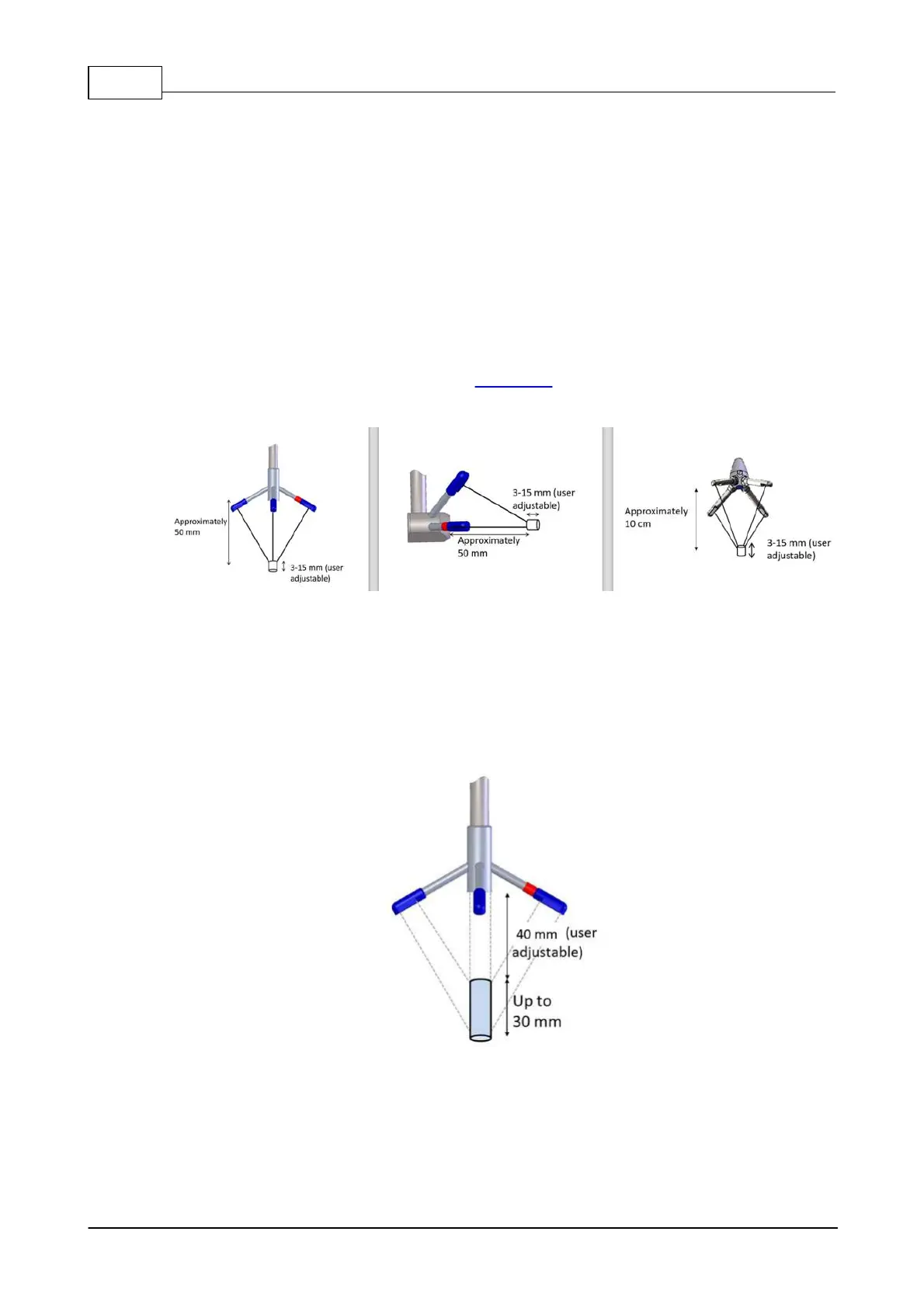
1.5.3 Vectrino Profiler
The mechanical and acoustic characteristics of the Vectrino and the Vectrino Profiler are identical;
both employ the same probe assembly and transducers. However, the Vectrino Profiler provides for
profiling over a 30 mm range interval thereby allowing measurement of the spatial structure of the flow
(see figure below).
The figure above shows how the beams intersect each other 50 mm from the transmitter. The
measurement profile is defined by this intersection and by range gating in time. Four passive
transducers, angled at 30° towards the center surround the central active transducer, allowing 3D
velocity measurements. With a profiling range up to 30 mm, a usable profiling region approximately
40-70 mm in height from the central transducer is provided. The Vectrino Profiler pulse intervals are
longer than the Vectrino because of the need to sample data from farther away.
 Loading...


