Comprehensive Manual8
© 2018 Nortek AS
1.1 Working Principle
The Nortek instruments measure the velocity of water by utilizing a physical principle called the
Doppler Effect. The Doppler Effect is the change in frequency of a sound wave when a wave source
moves with respect to an observer, or when the observer itself moves relative to the wave source.
You can hear the Doppler effect whenever a train passes by – the change in pitch you hear tells you
how fast the train is moving.
There are many ways to measure the Doppler Effect, each with its own advantages and drawbacks.
The Velocimeters measure velocity by transmitting a pair of short sound pulses of a specific
frequency into the water column. Part of the sound wave reflects back to the instrument, the
detected return signal will be further processed by the instrument. The reflected signal will be shifted
("Doppler Shifted") in accordance with the water velocity, which is what the processing is based on.
More details about that will follow.
The sound pulses do not reflect from the water itself, but rather from passive tracers suspended in
the water. These tracers or "scatterers" are typically zooplankton or suspended sediment that move
with the same average speed as the water, hence measured velocities corresponds to the water
flow. It is thus the moving particles that generates the change in pitch or frequency (the Doppler shift)
in the return signal that the instrument measure at.
The Velocimeters utilize a pair of short acoustic pulses with a known time lag, or separation, to
determine a Doppler induced phase shift. The use of two transmit pulses is commonly referred to as
a pulse-to-pulse coherent method. By utilizing this method the instrument is able to differentiate
relatively small differences in the velocities (corresponding to small differences in phase) and
therefore achieving great accuracy (often able to achieve velocity variance orders of magnitude lower
than standard incoherent Doppler systems) and low noise measurements. A limitation is the
maximum profiling range.
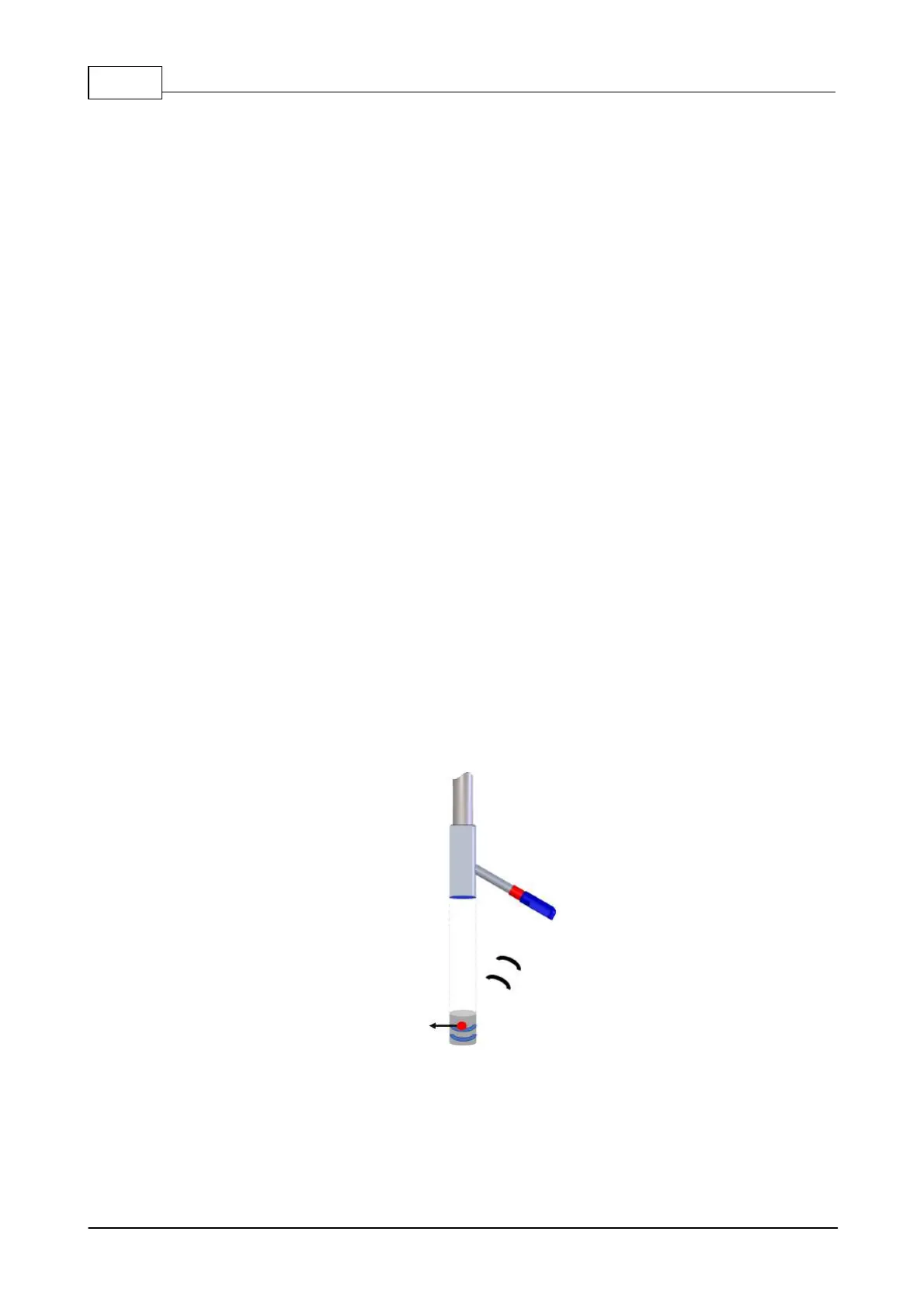
The figure below visualize how a sound wave transmitted through the central transducer (shown in
blue), hits a particle (red), which in next turn reflects parts of the sound (Doppler shifted - shown in
black) and the slanted beam which is the receiver arm which will detect the reflected sound wave.
Only one beam is shown for the sake of overview.
Figure: Transmit pulse
pair (blue), a moving
particle (red), and the
reflected, Doppler
shifted pulse (black)
Water flows can be measured in many different ways, depending on how accurate the
measurements need to be and how often the measurements need to be taken to detect the variation
of interest. As described in the section above, the Velocimeters use sound waves and the Doppler
 Loading...


