Comprehensive Manual10
© 2018 Nortek AS
and turbulence. It is therefore important to set the time lag properly. Information on what you need
to think about when setting this parameter can be found in the Using a Velocimeter chapter.
Near boundary measurements are prone to interference. This may happen if the first pulse is
reflected from a boundary and reach the sampling volume on its way back at the same time as the
second pulse is in the sampling volume. This is referred to as a Weak Spot.
1.2 Doppler Beams
All Acoustic Doppler Velocimeters send out short acoustic pulse pairs from the transmitter (center)
element. When the pulses travel through the focus point for the receiver beams, the echo is recorded
in each of the acoustic receiver elements and the phase shift between two consecutive is found. The
phase shift is then processed to find the actual velocity of the water, as described in the previous
section. The instrument samples on all three of four receivers simultaneously.
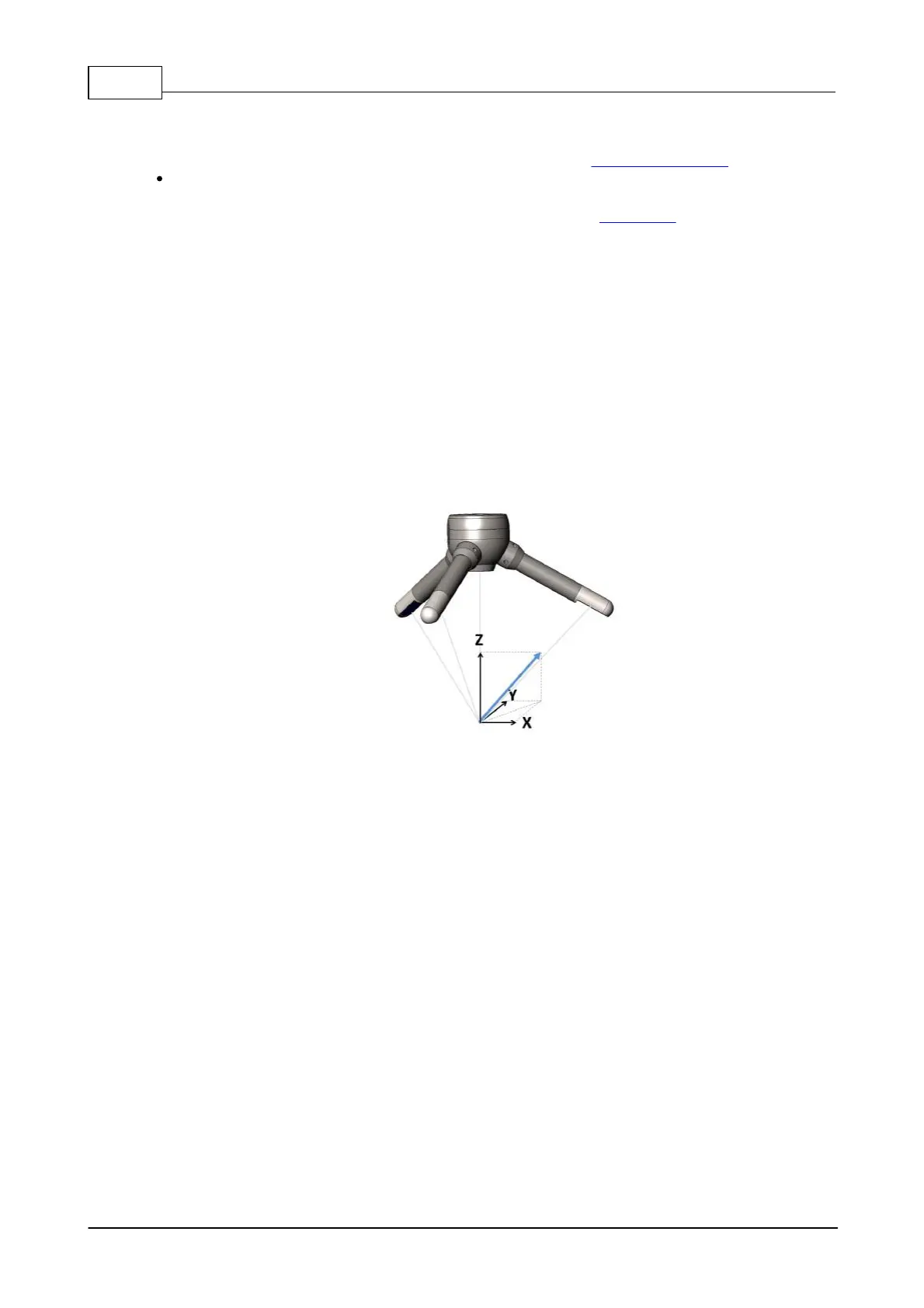
The Doppler shifts measured at the three or four receivers provide estimates of flow velocity along the
different beam directions, which are then combined geometrically to obtain the three orthogonal
components of the water velocity vector V (illustrated by the blue arrow in figure below). The
Velocimeters are in this way able to calculate 3D water velocity in the sampling volume by knowing
the exact orientation of the beams.
Figure: The blue arrow indicates a positive velocity.
The Vector, which is shown in the figure above has three receiver arms, while the Vectrino and the
Vectrino Profiler have four receiver arms. Because of the arrangement of the receiver arms, each pair
(composed of two opposing receivers) can measure the horizontal velocity component and the
vertical velocity component. Z1 and Z2 are the vertical velocity estimates associated with receivers 1
& 3 (X) and 2 & 4 (Y). For the standard downward looking probe, Z1 and Z2 are thus independent
measurements of the vertical velocity. Note that the side-looking probe does not have a secondary
measurement of the vertical velocity. Z1 will be the correct vertical velocity and Z2 should be output
as zero.
All Velocimeters go through a probe calibration procedure during its production. This to know the
exact geometry of the probe, and this information is saved in what we call head matrices. As long as
the sensor heads are not physically deformed, the head matrices will, consequently, remain the
same. This also means that the calibration only needs to be done once, and there is no need to re-
calibrate the probe again - unless it has physically been deformed.
A bistatic system
Bistatic geometries have been used with intersecting narrow beams to produce a measurement
volume in the intersection zone. A bistatic system is one where the transmitter and receivers are
physically separated; the transmitter generates sound along the vertical beam, and the receivers
listens for it. This results in motion along two axes, the component of motion of the object in the
direction of the transmitter and the component of motion in the direction of the receiver. The motion
 Loading...


