NFS2-3030/E Installation Manual — P/N 52544:N1 07/18/2014 31
Connecting the Loop Control and Expander Modules Installation
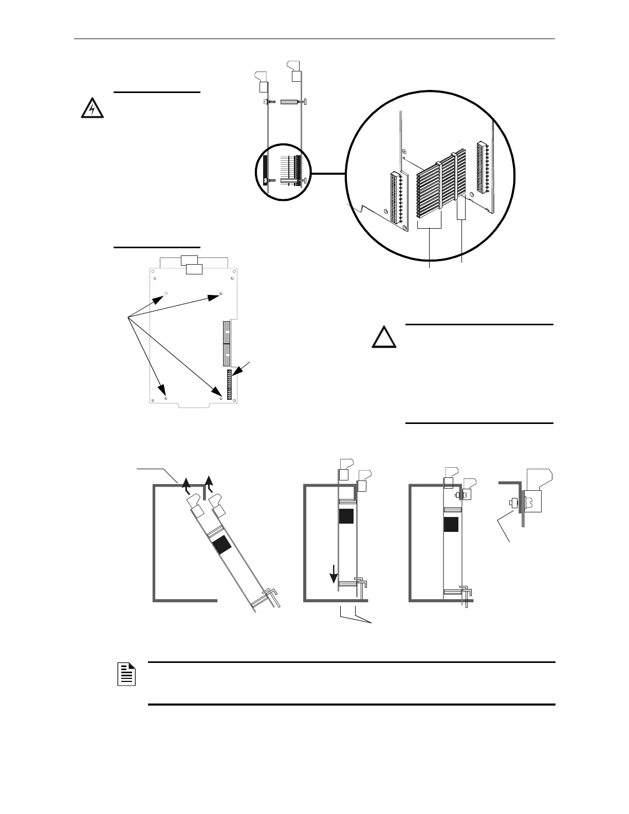
Figure 3.12 Connecting Loop Control Modules with Loop Expander Modules
Loop
Expander
Module
Loop
Control
Module
J1
J2
Loop
Expander
Module
Loop
Control
Module
The long-pin end plugs
directly into the back of
the Loop Control
Module board.
The short-pin end
plugs directly into
the top of the
Loop Expander
Module plug.
J2
Stand-off
locations
J2 on LCM-320
“LEM-320 Data”
Loop Expander Module mounted
behind Loop Control Module
LEM-LCM.cdr
CAUTION:
IF THE STACKER-CONNECTOR
IS INSTALLED UPSIDE-DOWN,
THE SHORT-PIN END OF THE
PLUG CAN FAIL TO MAKE A
SECURE CONNECTION WHEN
PLUGGED THROUGH THE LOOP
CONTROL MODULE.
WARNING: RISK
EQUIPMENT
DAMAGE.
USE SPECIFIED
STAND-OFF
MOUNTING
LOCATIONS ONLY.
SEE FIGURES 3.11
AND 3.12. DO NOT
USE CORNER
HOLES FOR
INSTALLATION
PURPOSES.
NOTE: Depending on system components, clearance may be tight. Do not force modules! Move
the assembly around gently until you find the angle where components and mounting studs pass
each other without scraping together.
voice-mount-mod.cdr
Chassis
Module
Screw
Top
Slot
Bottom
Slots
Figure 3.13 Inserting a Two-Layer Module into CHS-4N or CHS-M3 Chassis