Ts Series Installation and Operation Instructions │Trinity Ts
17
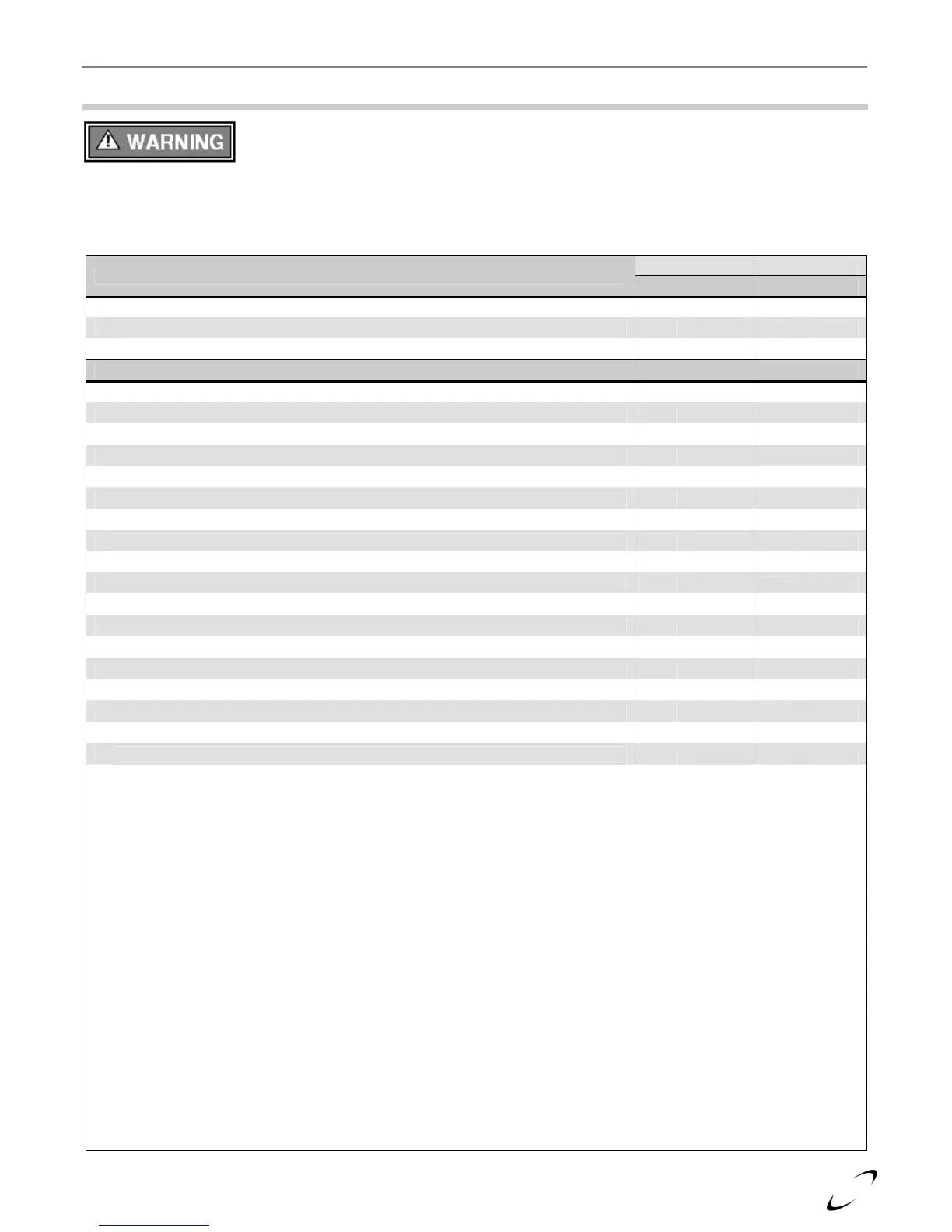
5.0 VENT/AIR-INTAKE TERMINATION CLEARANCES
The quick reference table below is to be read in conjunction with the numbered notes as
indicated, Figures 5-1 through 5-6, and the Venting Rules and Guidelines in Section 4.0.
The instructions detailed in this section are a combination of Trinity Ts specific and National Gas Code
restrictions. Compliance alone doesn’t insure a satisfactory installation as good common sense must also be
applied. Failure to follow these instructions may result in fire, property damage, serious injury or death.
Table 5-1 Termination Clearances Quick Reference Table
Canada
1
USA
2
Clearances to Air-Inlet Termination
Min. Distance Min. Distance
A Above grade/roofline and snow level
8
12 in. 305 mm 12 in. 305 mm
B Above roof line - Concentric Vent
6, 11, 13
24 in. 610 mm 24 in. 610 mm
C To exhaust vent from any other boiler 36 in. 915 mm 12 in. 305 mm
Clearances to Exhaust Vent Termination Min. Distance Min. Distance
D Minimum vertical separation above air inlet
9
18 in. 457 mm 18 in. 457 mm
E Minimum horizontal separation from air inlet
3
4 in. 102 mm 4 in. 102 mm
F Window, door or building opening 36 in. 915 mm 12 in. 305 mm
G To combustion air inlet from any other boiler 36 in. 915 mm 12 in. 305 mm
H Non-mechanical air supply inlet to building 36 in. 915 mm 12 in. 305 mm
I Mechanical air supply inlet to building
4
6 ft. 1.83 m 3 ft. 915 mm
J Soffit, overhang, eave or parapet 24 in. 610 mm 24 in. 610 mm
K Soffit vent or vent opening in an overhang, eave or parapet 6 ft. 1.83 m 6 ft. 1.83 m
L Outside corner
10
- - - -
M Inside corner of an L-shaped structure (including walls and fences) 36 in. 915 mm 36 in. 915 mm
N Electric meters, gas meters, regulators and relief equipment 6 ft. 1.83 m 4 ft. 1.22 m
P Each side of center line above or below meters, regulators and relief devices
5
36 in. 915 mm 36 in. 915 mm
Q Above a paved sidewalk, driveway, or parking lot on public property if adjacent
12
7 ft. 2.13 m 7 ft. 2.13 m
R Above a sidewalk, driveway, or parking lot on public property
X X X X
S Above a sidewalk, driveway on private property between / serving both dwellings
X X X X
T Under a concrete veranda, porch, deck, or balcony
7
24 in. 610 mm 24 in. 610 mm
U Above, under or near exterior stairs
X X X X
V Into a canopy or carport
X X X X
Notes:
1 - Canadian installations must comply with the current CSA B149.1 Natural Gas and Propane Installation Code and local
building codes.
2 - US installations must comply with current ANSI Z223.1/ NFPA 54 National Fuel Gas Code and local building codes.
3 - Horizontal separation center-to-center (c.c.) 4”-12” (102-305 mm). Refer to “Venting Rules and Guidelines” for
horizontal separation > 12” c.c. as it may impact vertical separation clearances.
4 - For US installations, an exhaust vent may be 3 ft above a mechanical air supply inlet if within 10 ft. [3 m] horizontally.
5 -
Horizontal clearance must be observed up to a height of 15 ft. [4.6 m] above/below the meter, regulator, or relief devices.
6 - Concentric Vent must protrude from the roof precisely 24” [610 mm] measuring from the terminal end-cap vanes.
7 - Permitted if veranda, porch, deck, or balcony is made of concrete and a minimum of two sides are fully open beneath.
8 - 24” is the recommended snow level allowance above grade/roofline or any surface that will support snow, debris, or ice
(i.e. for roof venting clearances - roofline and snow level). If living in a snowfall region, consult your local weather
office for the maximum typical snowfall for your area.
9 - Note that the vent must maintain a minimum vertical distance above the air inlet. Example: Vent height = 18” (457
mm) above air inlet + 12” (305 mm) for air inlet above grade/roof line and snow level = 30” (762 mm) above grade and
snow level.
10
- Clearances to an outside corner to be in accordance with local installation codes.
11
- In Canada, concentric vent materials are subject to approval by local inspectors. See Termination Kits in Section 4.0.
12
- Above public walkways, driveways or parking lots if adjacent to it and condensate cannot drip, freeze, or create a hazard.
13
- Contact the manufacturer for special exemptions relating to multiple boiler installations using concentric vents.
X - Not permitted by National gas code(s) and/or recommended by boiler manufacturer.