Trinity Ts │Installation and Operation Instructions Ts Series
30
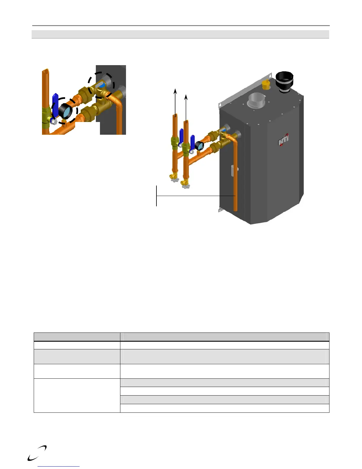
Figure 10-1 Ts80 Model
Near Boiler Piping
Boiler System Plumbing
The Trinity Ts boiler uses a low mass heat exchanger that requires a minimum rate of forced water circulation
any time the burner is operating (See Table 10-4 for minimum flow rates). To ensure the minimum flow rate is
attained, the boiler must be installed in a “Primary/Secondary” plumbing configuration utilizing “Closely Spaced
Tees” to de-couple the Boiler-Primary loop from the System-Secondary loop(s). See the examples of
Primary/Secondary Loop configurations in Figures 10-2 and 10-3.
System Components – As well as a Primary/Secondary Loop Configuration utilizing closely spaced tees a
properly installed system will include the following major components identified in Table 10-3 as a minimum.
Table 10-3 System Major Component Checklist
Factory Supplied Field Supplied Components
Pressure Relief Valve Boiler Loop Circulator (Pump B in Figure 10-2 or Pump C in Figure 10-3)
Pressure Gauge
DHW Loop Circulator (Pump A in Figure 10-2 and Figure 10-3, for applications
utilizing Indirect Fired Water Heater only)
Central Heat (CH) Loop Circulator(s)
(CH Circulator - Pump C in Figure 10-2; Zone Circulators in Figure 10-3)
Central Air Removal Devices (i.e. Micro Bubbler or Air-Scoop)
Pressure Regulating “Fill Valve”
Backflow Preventor
Expansion Tank
Connect to boiler and
system plumbing. Refer
to Figures 10-2 and 10-3.
Inlet
Outlet
Pressure Relief
Valve discharge
to floor drain
Pressure Relief
Valve
Pressure
Gauge