Trinity Ts │Installation and Operation Instructions Ts Series
36
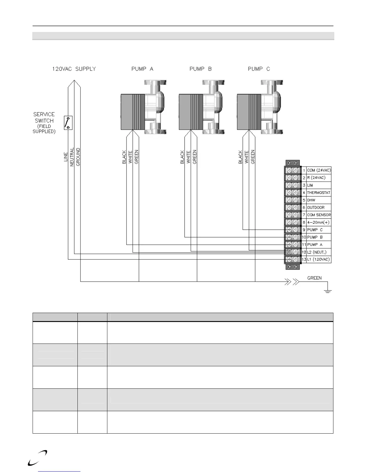
Figure 11-1 Ts80 Model
Line Voltage Field Wiring
Table 11-1 Line Voltage Field Connections
Connection Location Description
PUMP C 9
120VAC output to the Central Heating circulator; powered during a demand for Central
Heat (Thermostat).
PUMP B 10
120VAC output to the Boiler circulator; powered during all demands for DHW, and
Central Heat (Thermostat). This output is not used for all plumbing configurations, see
"Field Wiring".
PUMP A 11 120VAC output to the DHW circulator; powered during a demand for DHW.
L2
(NEUT.)
12 Location for connecting neutral of the power supply and all circulators.
L1
(120VAC)
13
Location for connecting line voltage of the power supply. Note most installation codes
require the installation of a service switch to break line voltage to the appliance.