Field Wiring │ Vmax I&O Manual
Treatment - Boiler water that falls outside of the conditions listed above must be treated with a corrosion
inhibitor. For information on performing the treatment, follow the instructions included with the corrosion
inhibitor. See Table 10-1 for a list of recommended boiler system cleaners and corrosion inhibitors.
To maintain protection, the level of corrosion inhibitor must be monitored periodically
for the correct concentration.
Anti-freeze - For systems requiring freeze protection, use only inhibited propylene glycol, specially formulated
for hydronic heating systems; use of other types of antifreeze may be harmful to the system and will void the
warranty. Note: the use of glycol may reduce the usable output capacity of the boiler, thus requiring the unit
to be “down-fired” by limiting the maximum operating capacity and/or the maximum water temperature. NTI
recommends against exceeding 35% concentration of glycol.
DO NOT use inhibited glycol with non-compatible boiler inhibitors. Non-compatible
inhibitors may counteract each other rendering them ineffective.
Near Boiler Plumbing (Central Heating)
Pressure Relief Valve - A Pressure Relief Valve is factory supplied with each unit. Vmax VM110 and VM110P
boilers have a maximum allowable operating pressure of 30 PSI. The pressure relief valve must be installed
in the vertical position, as illustrated in Figures 10-1, 10-2(a), 10-2(b) and 10-3(a), with the drain pipe outlet
exiting the side of the pressure relief valve horizontally. Pipe the outlet of the relief valve towards the floor,
away from where it could be harmful.
If installed in the incorrect orientation (horizontally with drain pipe out the bottom) the
relief valve may not function properly resulting in property damage or personal injury.
Ensure the discharge of the pressure relief is piped to a location where the steam or water
will not cause property damage or serious injury.
Pressure Gauge – Vmax VM110 and VM110P units come with a factory supplied 60 PSI Pressure Gauge. The
pressure gauge must be installed at the boiler outlet prior to any circulators. See Figures 10-2(c) and 10-3(b).
Low Water Cutoff (LWCO) – Vmax boilers are provided with a factory installed Water Pressure Sensor. The
sensor provides a reading of the boiler inlet water pressure on the display; in the event the pressure drops
below 7 PSI, the control will go to a blocking error “FILL”, inhibiting burner operation. Where required by
the Authority having jurisdiction, an external LWCO may have to be installed; see Figure 10-1.
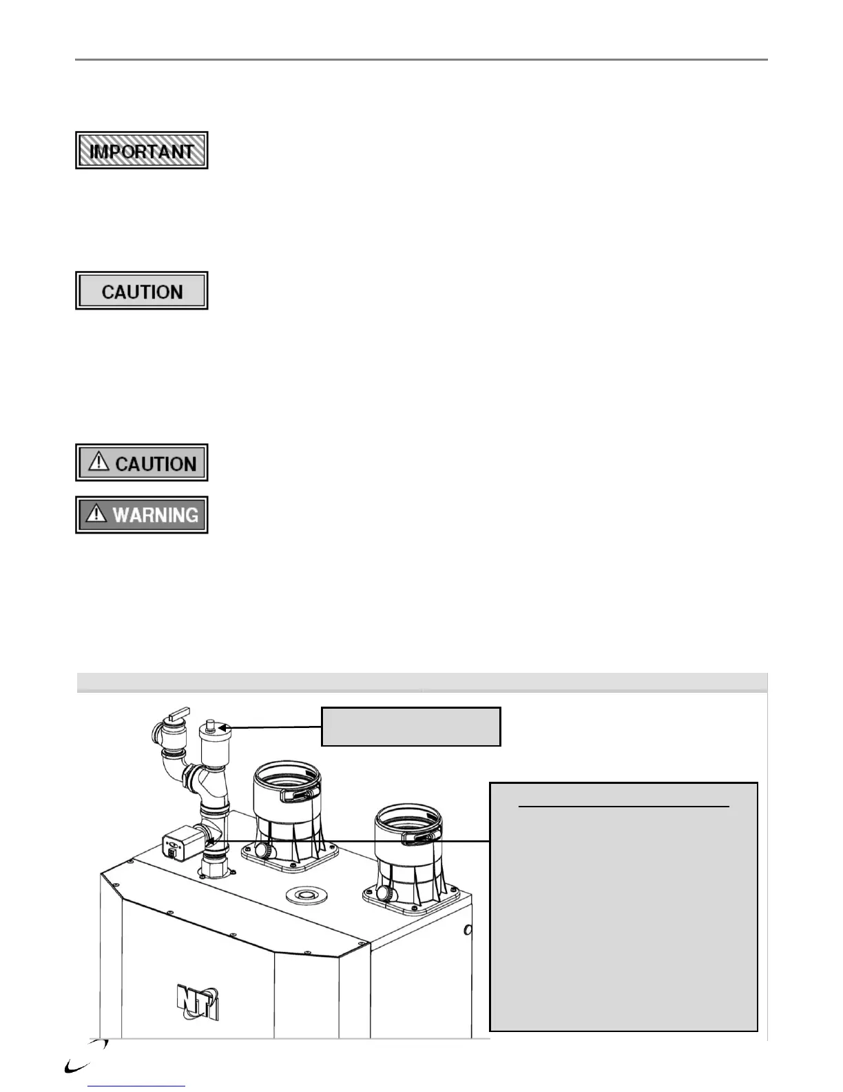
Figure 10-1 Installation of Optional LWCO
Low Water Cutoff Location
(when required by local authorities)
Install the LWCO in a suitable tee (reference
installation instructions provided with the
LWCO) as illustrated. DO NOT install
isolation valves between the boiler and the
LWCO. The LWCO switch must be wired to
break the boiler limit circuit or line power to
the boiler (see Section 12.0 – Field Wiring).
NTI offers the following LWCO kits:
VM110 LWCO Kit – P/N TBD
VM110P LWCO Kit – P/N TBD
When the installation is complete, TEST
THE LWCO to ensure the burner shuts
down when the water level drops.
Auto Air Vent – keep open to
avoid false trips of the LWCO