Vmax I&O Manual │Field Wiring
Boiler System Plumbing
Vmax boilers use a low mass heat exchanger that requires a minimum of 3.5 GPM of forced water circulation
any time the burner is operating. To ensure the minimum flow rate is attained, carefully following the plumbing
instructions in this section.
Circulating Pumps (VM110) – VM110 models incorporate a Central Heat Pump and “Primary Loop” with
“Closely Spaced Tees”; therefore, only the DHW Pump ( Indirect Fired Water Heater Pump) needs to be
sized to ensure adequate water flow through the boiler. See Table 10-2 and Figure 10-4 for assistance in
sizing the DHW Pump for Vmax model VM110.
Circulating Pumps (VM110P) – Vmax Plus models incorporate a Boiler Pump, Diverter Valve and “Primary
Loop” with “Closely Spaced Tees” (Note: the Primary Loop is field installed below the boiler – see Figure 10-
3(b)). Sizing circulators to ensure minimum flow through the VM110P boiler is NOT necessary.
Circulating Pump Outputs – Vmax boilers are equipped with three 120VAC pump outputs:
1. DHW PUMP - operates during a Domestic Hot Water demand (DHW). The DHW PUMP output is not
used on VM110P (Plus) models.
2. CH PUMP - operates during a Central Heat demand (CH). The VM110 internal pump is factory wired to
the CH PUMP output.
3. BOILER PUMP - operates during any demand. The VM110P (Plus) internal pump is factory wired to the
BOILER PUMP output. NOTICE: the BOILER PUMP output is only used to operate boiler pump of a
VM110 that is part of a cascade system, see Figure 13-1.
Ensure circulating pumps are oriented as per the manufacturers’ instructions. Wiring of these circulators will
depend on the system configuration selected; see Figures 10-5 through 10-9. For further wiring details see
Section 12.0.
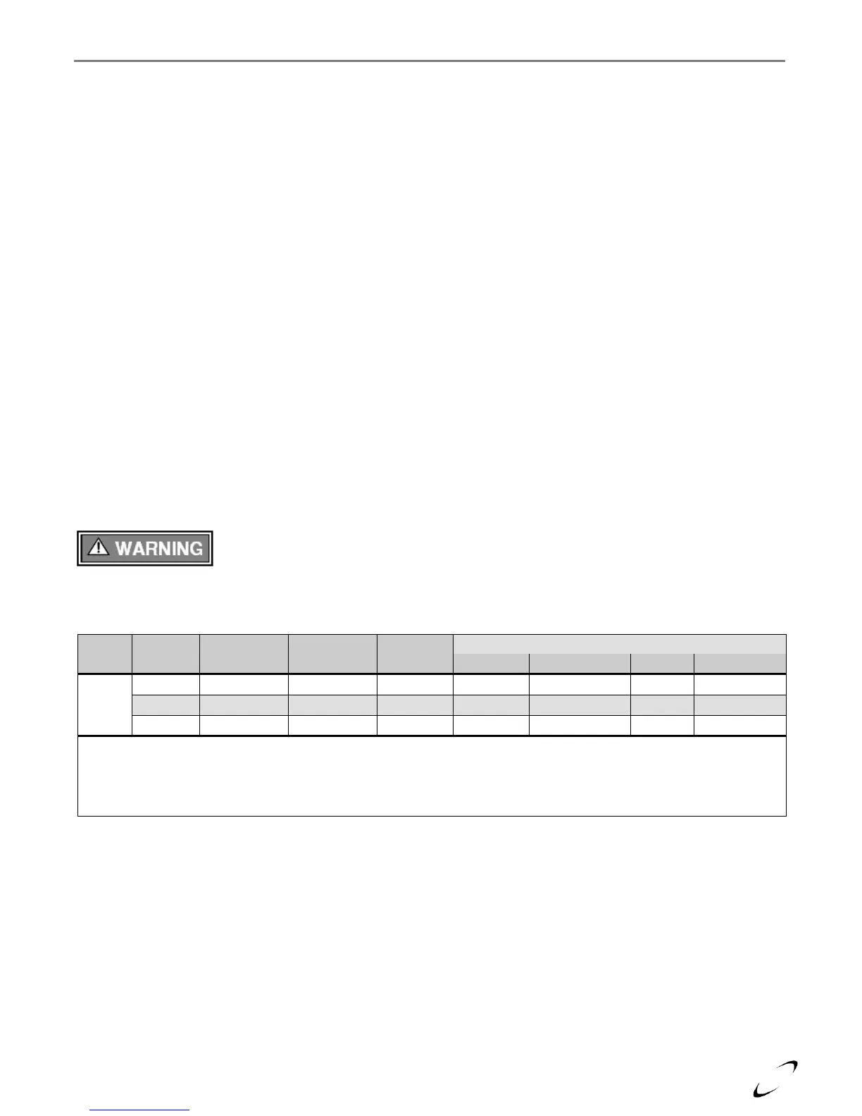
Failure to ensure the minimum water flow rate through the boiler when the burner is
operating will result in “short-cycling”, reduced performance and operating efficiency,
and may also cause overheating and premature failure which will void the warranty. Failure to follow
instructions may result in fire, property damage, serious injury or death.
Table 10-2 VM110 DHW Circulator and Pipe Size Requirements
Minimum Primary Loop Pump Size
Notes:
1
Pump sizing accounts for the head loss associated with the boiler, a Trin & Stor S40 Indirect Water Heater and up to 30
equivalent feet of the specified minimum pipe diameter.
2
Only the pump responsible for generating flow through the Indirect Water Heater connected to a VM110, needs to be
sized to ensure adequate flow rate through the boiler.