Cascade Instructions │ Vmax I&O Manual
13.0 CASCADE INSTRUCTIONS
The Vmax controller has the internal capacity to cascade (lead-lag / stage) up to 16 VM110 boilers, without the
use of an external controller. Use the instructions detailed in this section to set-up and install the cascade system.
Vmax Plus (VM110P) – NTI recommends against cascading multiple Vmax Plus boilers
together.
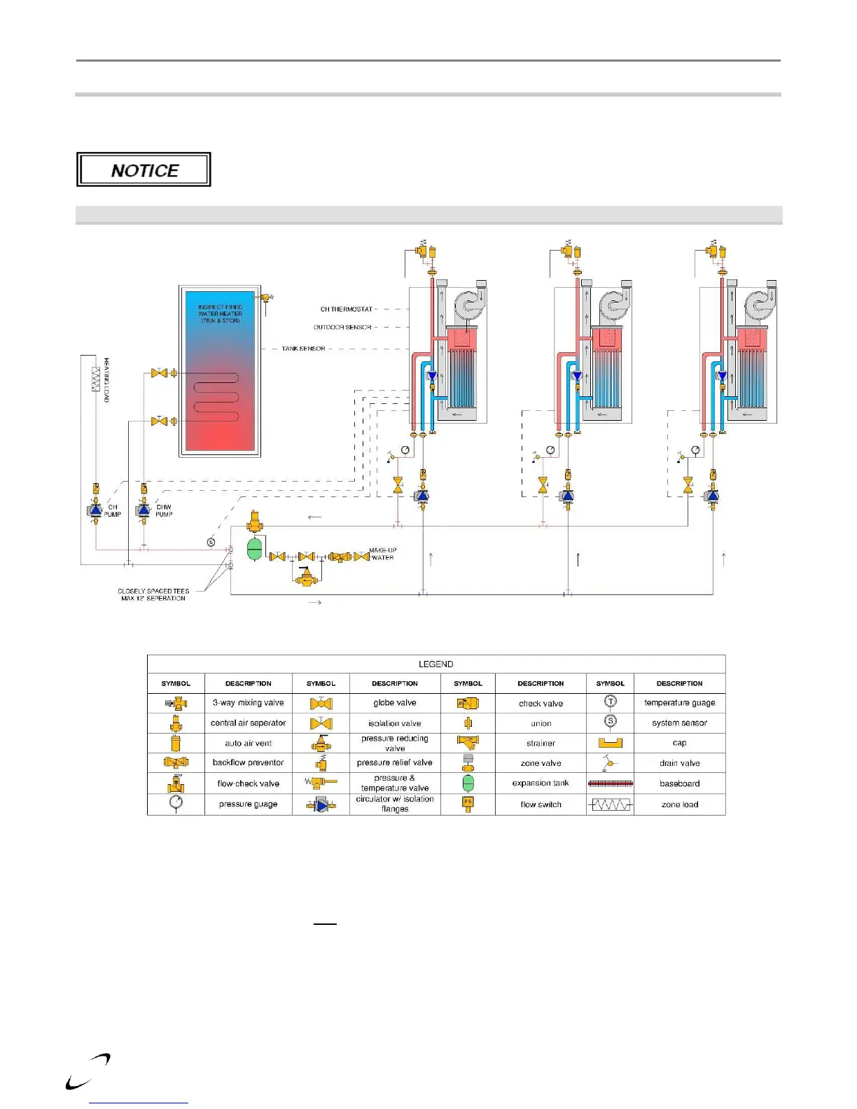
Figure 13-1 VM110 Cascade Plumbing Schematic
Communication Wiring – for each boiler in the cascade, wire in parallel electrical connections Argus Link (-)
and Argus Link (+), terminals 1 and 2 (see Figure 12-2).
Establish Managing Boiler – choose one boiler to be the Managing Boiler, this boiler will receive all control
wiring and will be used for setting control parameters (see steps below). All non-Managing Boilers must have
the “S4” switch (located on the top right side of the control) switched OFF. *
*Note: the “S4” switch is factory set to ON. The switch is in the off position when it is closest to the “S4”
marking. The “S4” switch must remain in the ON position on the Managing Boiler.
Plumbing – install the boilers in parallel in a primary/secondary plumbing configuration as illustrated in Figure
13-1.