Field Wiring │ Vmax I&O Manual
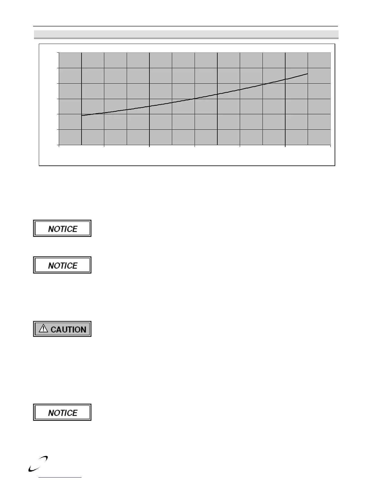
Figure 10-4 VM110 Head Loss Curve (Only Applicable for DHW Demands)
Air Removal – The boiler and system plumbing layout must be configured to promote the removal of air from
the water. Air vents and bleeders must be strategically placed throughout the system to aid in purging the air
from the system during commissioning of the boiler. The system must also employ the use of a strategically
located air removal device, such as an air-scoop or micro-bubbler, designed to remove the air from the water
as it flows through the system.
Follow the installation instructions included with the air removal device when placing it
in the system; air removal devices generally work better when placed higher in the
system. Always locate air removal devices in areas of the system that have a guaranteed
positive pressure, e.g., in close proximity to the water fill and expansion tank.
Vmax VM110 & VM110P boilers are equipped with an automatic air vent to aid in
purging of air from the boiler during the initial fill. This air vent is not intended to be the
primary air removal device in the system.
Expansion Tank – The expansion tank must be sized in accordance with the water volume of the system as well
as the firing rate of the appliance. It is important to locate the expansion tank, and make-up water fill, on the
inlet side of any circulator in the system, as doing so will guarantee the lowest pressure in the system will be
at least equal to the tank and make-up water pressure. See examples in Figures 10-5 through 10-9.
Ensure the expansion tank cannot become isolated from the boiler anytime the system is
operating. The installation of flow checks, motorized valves or other shutoff devices
(other than for the purpose of servicing) are not permitted between the outlet of the boiler
and the expansion tank; see Figures 10-5 through 10-9. Failure to follow these
instructions may result in discharge of the Pressure Relief Valve resulting in property
damage or personal injury.
Indirect Fired Water Heater (IWH) – If installing an IWH with a VM110, there are various installation
options to be considered, consult Figures 10-2 and 10-5 through 10-7 for specific examples. The Vmax
VM110P (Plus) incorporates an IWH, one cannot be installed external to the unit.
Figures 10-5 through 10-9 illustrate typical piping systems. These piping schematics do
not illustrate all of the required concepts and components required to have a proper
installation. Concepts not shown include: prevention of thermal-siphoning (heat traps),
isolation valves, drain and purge valves, etc. It is the responsibility of the installing contractor and system
designer to determine which system best meets the need of the installation and to consider all aspects of a proper
system design. Contractor modifications to these instructions may be required, based upon existing piping and
system design; consult NTI for required assistance (1-800-688-2575).