3 Supported Interfaces
This section describes the DPU Controller supported interfaces. Each numbered interface referenced
in the figures is described in the following table with a link to detailed information.
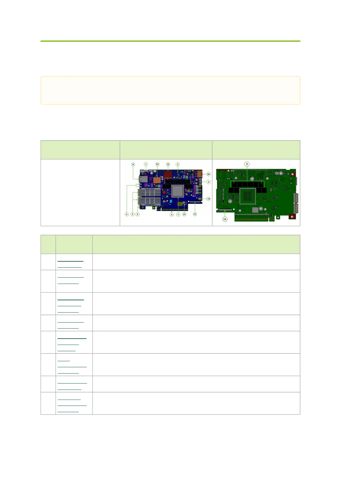
3.1 FHHL DPU Controller Layout and Interface
Information
OPN DPU Controller Component Side DPU Controller Print Side
900-9D3C6-00CV-GA0
900-9D3C6-00CV-DA0
Ite
m
Interface Description
1 System-on-
Chip (SoC)
16 Arm-Cores SoC
2 Networking
Interface
The network traffic is transmitted through the DPU ControllerQSFP112 connectors. The
QSFP112 connectors allow the use of modules and optical and passive cable
interconnect solutions
3 Networking
Ports LEDs
Interface
One bi-color I/O LEDs per port to indicate link and physical status
4 PCI Express
Interface
PCIe Gen 5.0 through an x16 edge connector
5 DDR5 SDRAM
On-Board
Memory
20 units of DDR5 SDRAM for a total of 48GB @ 5200MT/s. 128bit + 16bit ECC, solder-
down memory
6 NC-SI
Management
Interface
NC-SI 20 pins BMC connectivity for remote management
7 USB 4-pin RA
Connector
Used for OS image loading
8 1GbE OOB
Management
Interface
1GbE BASE-T OOB management interface
The below figures are for illustration purposes only and might not reflect the current
revision of the DPU Controller.
 Loading...