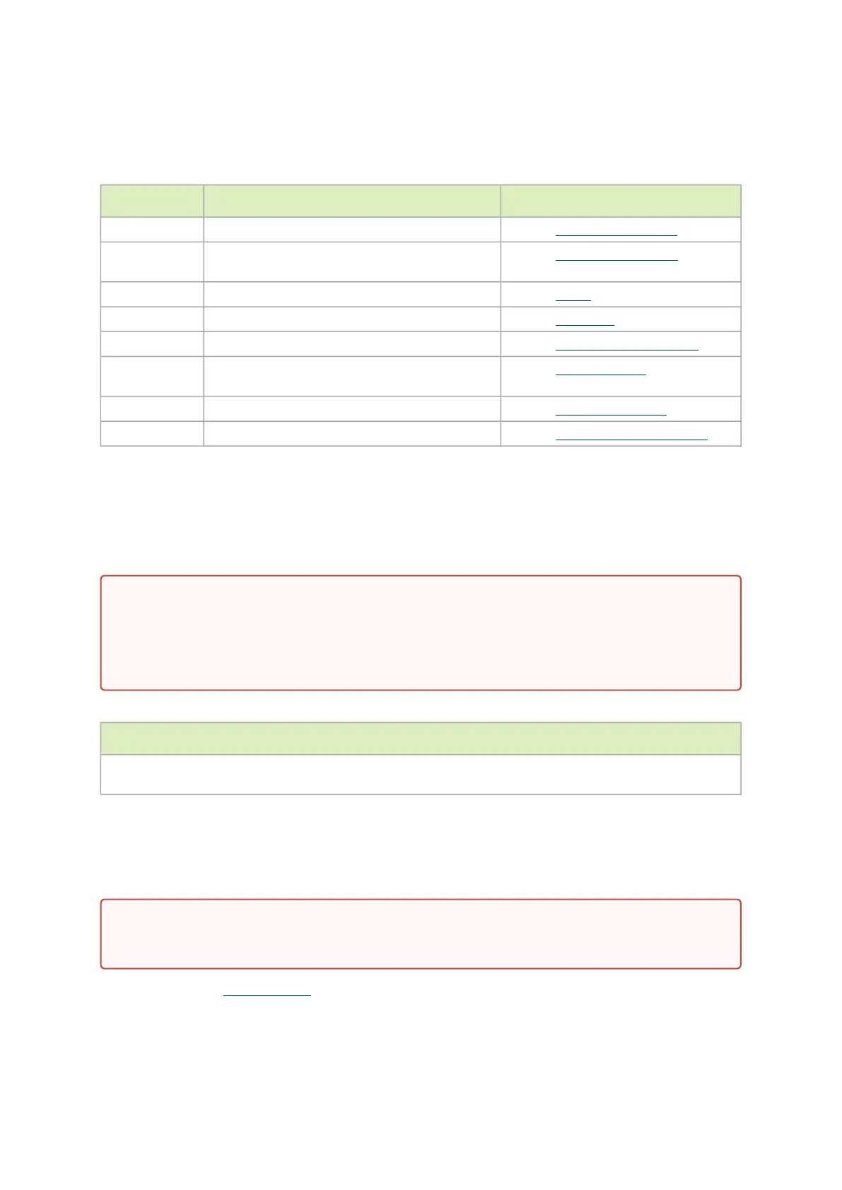
5.2 Installation Procedure Overview
The installation procedure of DPU involves the following steps:
Step Procedure Direct Link
1 Check the system’s requirements. Refer toSystem Requirements
2 Pay attention to the airflow consideration within
the host system
Refer toAirflow Requirements
3 Follow the safety precautions Refer to Safety
4 Unpack the package Refer toUnpacking
5 Follow the pre-installation checklist Refer toPre-Installation Checklist
7 Install the DPU according to the form-factor you
have purchased.
Refer toDPU Installation
8 Connect cables or modules to the DPU Refer toCables and Modules
9 Power-up the DPU Refer toDPU Power-Up Instructions
5.3 System Requirements
5.3.1 Hardware Requirements
The below table lists the motherboard and power supply requirements per DPU series.
Power Supply Requirement
Require a supplementary 8-pin ATX power supply connectivity available through the external power supply
connector.
5.3.2 Airflow Requirements
The DPU Controller is offered with one airflow direction: from the heatsink to the network ports.
Please refer to the Specificationssection for airflow numbers per DPU model.
Unless otherwise specified, products are designed to work in an environmentally controlled
data center with low levels of gaseous and dust (particulate) contamination.
The operating environment should meet severity level G1 as per ISA 71.04 for gaseous
contamination and ISO 14644-1 class 8 for cleanliness level.
Any use of the product in the opposite airflow direction (from network ports to heatsink)
must be validated thermally to ensure proper cooling of the product.
 Loading...