USB and PCIe
PRELIMINARY INFORMATION
Jetson Orin NX Series and Jetson Orin Nano Series DG-10931-001_v1.1 | 30
7.1 USB
Orin module supports up to three USB 2.0 ports and up to three USB 3.2 ports. Two examples
are shown in Figure 7-1 and Figure 7-2. Polarity inversion (P/N swapping) is supported for the
USB 3.2 interfaces.
Note: Some non-compliant USB 3.0 devices will not function correctly unless USB 3.2 Gen2 is
disabled.
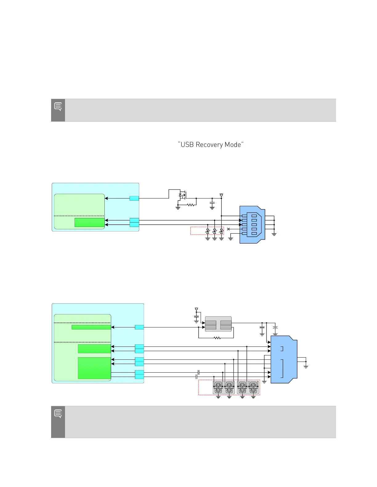
The example shown in Figure 7-1 is for connections to a USB device only connector to be used
to support recovery mode (See Section 3.2 for details on recovery mode)
or a USB device if booted normally. A USB Micro B connector is shown in the example.
Figure 7-1. USB Micro B USB Device and Recovery Connection Example
Jetson
SoC
USB 2.0
HS_USB0_P0_N
HS_USB0_P0_P
GPIOx
USB0_D_N
USB0_D_P
*
111
109
VDD_5V_USB
VBUS
DN
DP
ID
GND
SH1
SH2
SH3
SH4
MSP5.0A
-M3/8 9A
G
S
D
1M
0.1uF
Micro B
VBUS Detect
The example shown in Figure 7-2 is for connections to a USB 3.2 Type A connector to support
host only. Recovery mode is not supported.
Figure 7-2. USB 3.2 Type A Host Only Connection Example
Jetson
SoC
UPHY_RX1_N
UPHY_RX1_P
UPHY_TX1_N
UPHY_TX1_P
USB 3.1
& PEX
HS_USB0_P0_N
HS_USB0_P0_P
USB1_D_N
USB1_D_P
USBSS_RX_N
USBSS_RX_P
USBSS_TX_N
USBSS_TX_P
GPIO00
GP45_USB_VBUS_EN0
UART
87
117
115
166
168
161
163
Load Switch
EN OC
IN OUT
100
0.1uF
0.1uF
VDD_5V_IN
TPD4E05U06
VBUS
DN
DP
GND
RX_N
RX_P
GND
TX_N
TX_p
USB 2.0
USB 3.1
TAB
TAB
USB SS
Type A
Notes:
1. AC capacitors should be located close to either the USB connector, or the Orin module pins.
2. Connector used must be USB Implementers Forum certified if USB 3.2 is implemented.
 Loading...


