NVIDIA Jetson TX2/TX2i OEM Product Design Guide
JETSON TX2/TX2i OEM PRODUCT | DESIGN GUIDE | 20180618 37
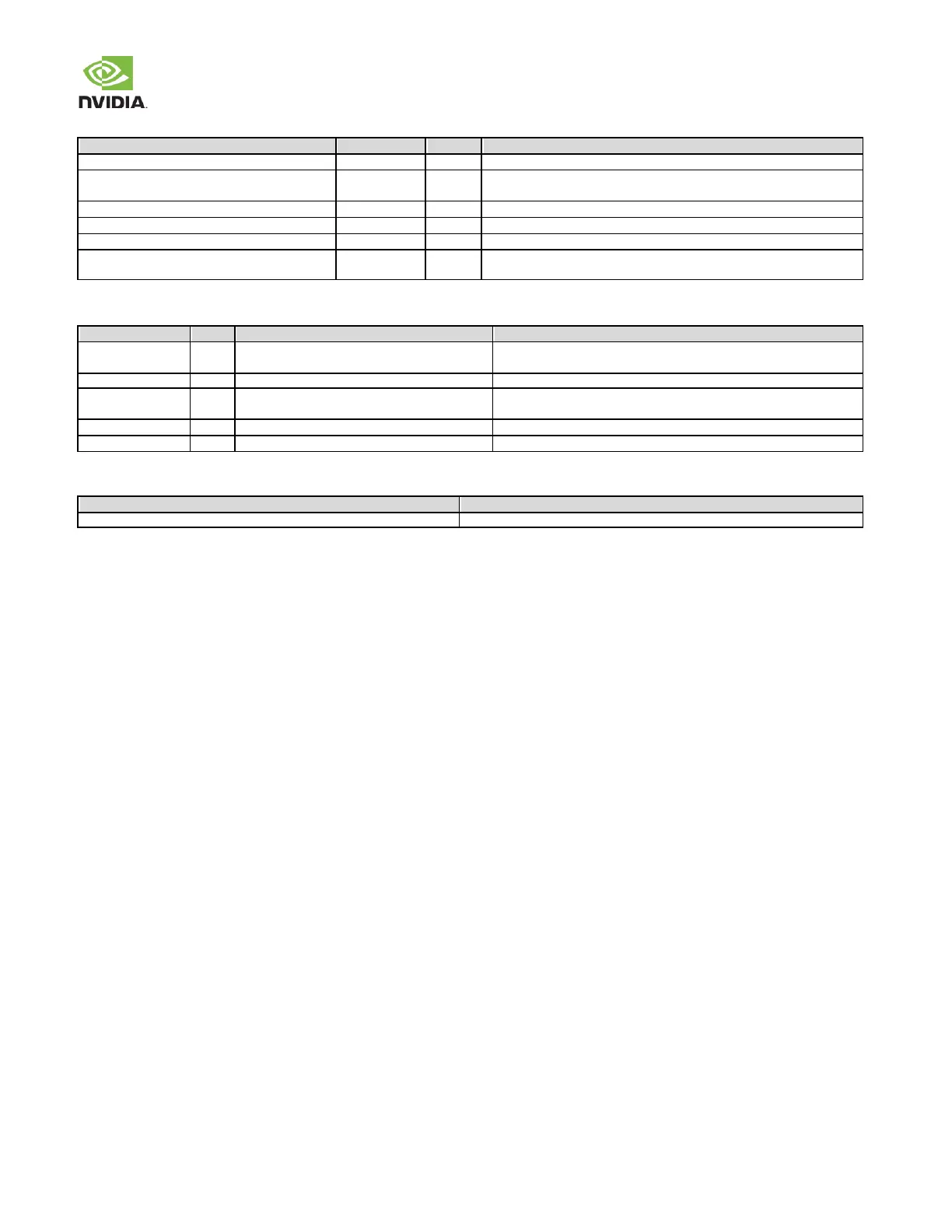
Table 30. Ethernet MDI Interface Signal Routing Requirements
Trace Impedance Diff pair / Single Ended
±15%. Differential impedance target is 100. 90can be used if 100
is not achievable
Min Trace Spacing (Pair-Pair)
Max Within Pair (Intra-Pair) Skew
Ideally there should be no vias, but if required for breakout to Ethernet
controller or magnetics, keep very close to either device.
Table 31. Ethernet Signal Connections
ESD device to GND per signal
Gigabit Ethernet MDI IF Pairs: Connect to Magnetics +/ pins
GND
Gigabit Ethernet ACT : Connect to LED1C on Ethernet connector.
GND.
Pull-down to GND (exists on the module)
Gigabit Ethernet Link 100 : Connect to LED2C on Ethernet connector.
Pulldown part of strapping to use 3.3V PHY mode.
GND
Gigabit Ethernet Link 1000 : Connect to Link 1000 LED on conn.
Table 32. Recommended Gigabit Ethernet observation (test) points for initial boards
One for each of the MDI[3:0]+/– lines.
Near the module connector & Magnetics device.