Functions of external devices for ASIL D applications
Safety Manual for MPC5777M, Rev. 1.1
NXP Semiconductors 61
Assumption: [SCG18.093]If the MPC5777M is signalling a failure via its error output pin(s), other output
pins can not be relied on. [end]
4.5.1 Both FCCU pins connected to external device
Depending on user selection, there are two different ways to interface to the FCCU:
• Both FCCU pins connected to the external device
• Only a single FCCU pin connected to the external device
The user can choose between these two FCCU configurations, depending on which best fits the hardware
and software system.
Assumption: [SM_FMEDA_120] If both error out pins are connected to the external device, the external
device itself shall check both signals, taking into account the behavior of the two pins as defined in Table 3.
[end]
In this configuration the external device continuously monitors the output of the FCCU. Thus it can detect
if the error out pins are not working properly. The advantage of the two pin configuration with respect to
the single pin option is that it does not require any dedicated software.
NOTE
Implementation hint: Monitoring the error output pins through a
combinatorial logic (for example, XOR port) can generate some glitches.
Oversampling these pins reduces the possibility that the glitches occur. A
functional reset has no affect on FI[0], but it sets FI[1] to high-impedance
with a pull-up. To avoid changing FI[1] during a functional reset when
time-switching or bistable protocol is used, it is recommended to configure
FCCU_CFG[PS] = 0.
4.5.2 Single FCCU pin connected to external device
In this configuration, only the FI[0] pin is connected to the external device. If a fault occurs, the FCCU
communicates it to the external device through the FI[0] pin.
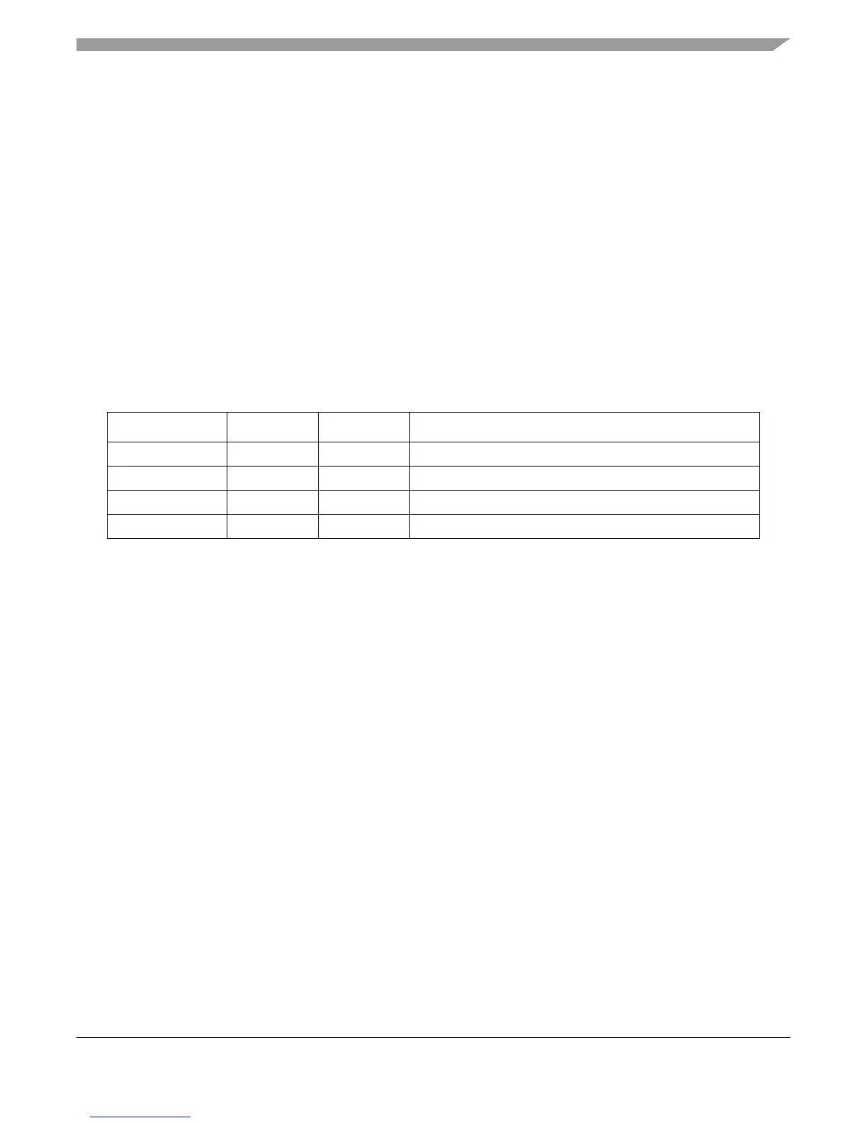
Table 3. FCCU EOUT pin behavior
1
1
See “EOUT interface” section in the “Fault Collection and Control Unit (FCCU)” chapter of the MPC5777M
Reference Manual for details. If Error phase is accompanied by a functional reset, FI[1]/EOUT1 becomes high-z
with weak pull-up, while FI[0]/EOUT0 behaves as described.
2-pin protocol FI[1] FI[0] Definition of faulty state
Bi-stable 1 0 Two pins are out of phase and FI[0] is low
Time switching 1 0 Two pins are out of phase and FI[0] is low
Dual rail toggle_inv toggle_inv Tow pins are not out of phase
Dual rail 1 toggle_inv Two pins are not out of phase

 Loading...


