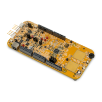
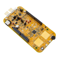
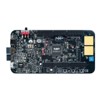
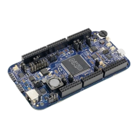
5. Board interface connector
This chapter provides a useful cross reference to see the connection from the motherboard to the board
interface connector, and what MCU pins are connected to the interface connector on the daughter card.
Table 14 lists all the connections to the board interface connector on both motherboard and daughter
card. The table on the left lists the 240 connections for the first interface connector (J28), the table on
the right lists the 240 connections for the second interface connector (J29):
• The column ‘Motherboard’ shows the motherboard connections to the interface connectors like
power supply connections and user area port pins.
• The column 257 BGA shows the connections from the MCU pins to the interface connector on
daughter card for the 257 BGA package. It is ensured that the MCU port pins are routed to the
associated user area port pin on the motherboard, but in some cases due to pin multiplexing uses
this is not possible. The schematic signal name is included in brackets, but for all possible
multiplexing functions of each pin please see the device reference manual.
• Green fields indicate power signals, power signals are connected to all the appropriate pins on
the MCU
• Red fields indicate MCU signals that are only connected to the motherboard via 0-ohm links or
jumpers that are not populated by default to preserve signal integrity. To use these signals for
functions other than available on the daughter card add a jumper, or for links populate the link or
short the pads with a solder blob.
• Blue fields indicate MCU signals that have dedicated connections to the motherboard peripherals
through the interface connector (such as the CAN and FlexRay).
• Ground signals are not listed here. A solid ground connection is achieved through the middle bar
of the interface connector.
 Loading...