HeatWater.com | WaterService@nyle.com | (800) 777-6953 IM-e360-122023 IM-e360-122023 HeatWater.com | WaterService@nyle.com | (800) 777-6953
17
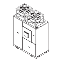
Figure 7: Center of Gravity Diagram
37
15
16
"
39
7
16
"
19
5
8
"
Seismic Mounting
Local area seismic or vibration considerations should
be addressed with eld supplied, additional equipment
as per applicable codes, regulations, and best practice.
Seismic mounts and vibration control measures should
be evaluated and determined by a qualied engineer. If
whole-unit spring mounts are used, it may be necessary
to adjust spring feet tension on the heat pump’s com-
pressor, and/or to provide blocking and tighten the spring
feet fully, to prevent resonance between the whole-unit
and compressor spring mounts.
CAUTION
After placing the heat pump, ensure that the unit is level
front to rear and side to side, adjusting as necessary,
before afxing the unit to the mounting base with the
provided base clips. Units that are not level will not drain
properly, and may vibrate excessively.
Mounting the Fans
e-Series units may have the fans shipped separately.
The installer must decide whether to install the fans
prior to unit mounting, or after the unit is securely
mounted in place.
All non-ducted applications must enclose the fans and
direct air away from the intake (back) of the unit. A duct-
less fan shroud accessory is available for this purpose.
CAUTION
Fans are heavy objects and must be handled with care.
When lifting, support the fan assembly on two sides at all
times to avoid torquing the fan support structure, and only
lift from the bottom support plate of the fan. Lifting from
the top plate may torque the fan assembly out of spec and
cause nuisance issues, noise, or equipment failure.
When mounting a fan, be sure to mount such that
the fan’s cable ttings are positioned as close as
possible to the fan electrical ports on the top of
the heat pump. Once securely fastened, connect the
heat pump’s fan wiring to the fans.
1. If shipped separately, the fans may require their in-
take air grids to be attached prior to installation.
2. Take care to line up the fan base plates with the
supplied mounting holes for bolt attachment with
the supplied bolts.
3. Afx all attachment points securely.
4. Attach Fan wiring as descrbed in “Fan Wiring” on
page 18.
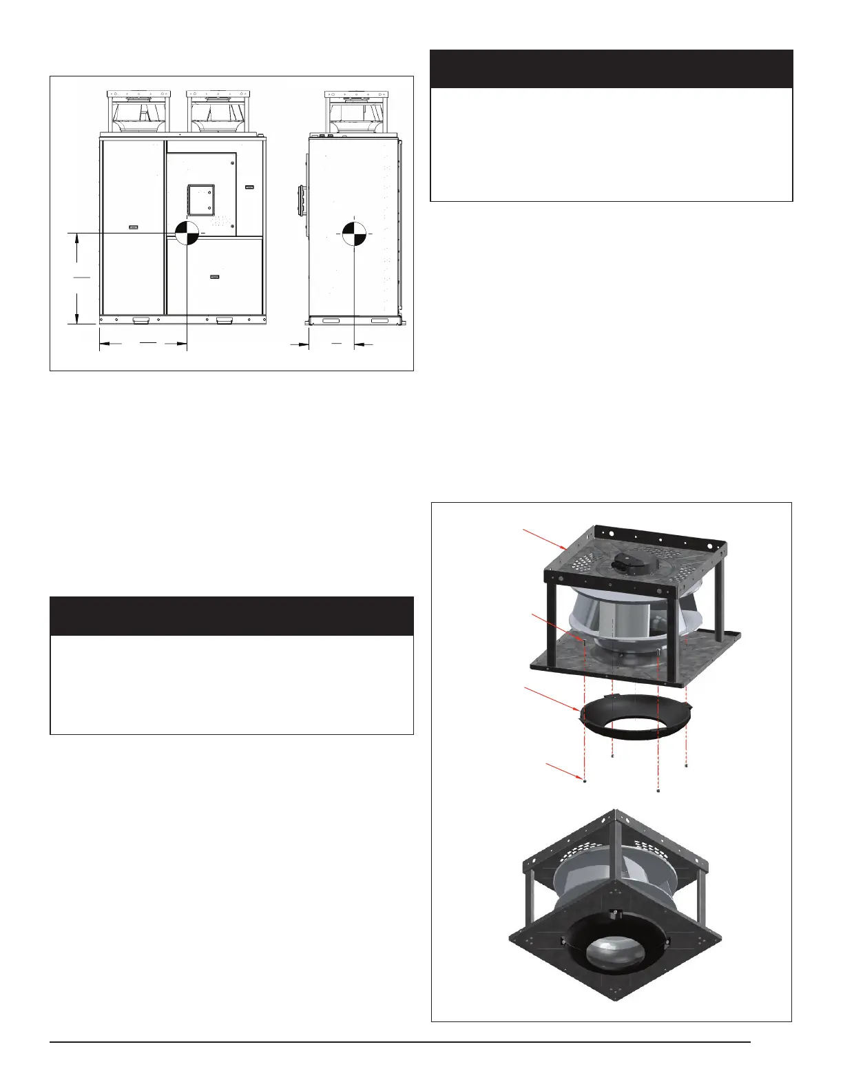
Figure 8: Fan Intake Air Grid Installation
FLOWGRID
4X - 3/8"
NYLON LOCKNUT
4X - 3/8"
HEX BOLT
PLUG FAN