HeatWater.com | WaterService@nyle.com | (800) 777-6953 IM-e360-122023
20
IM-e360-122023 HeatWater.com | WaterService@nyle.com | (800) 777-6953
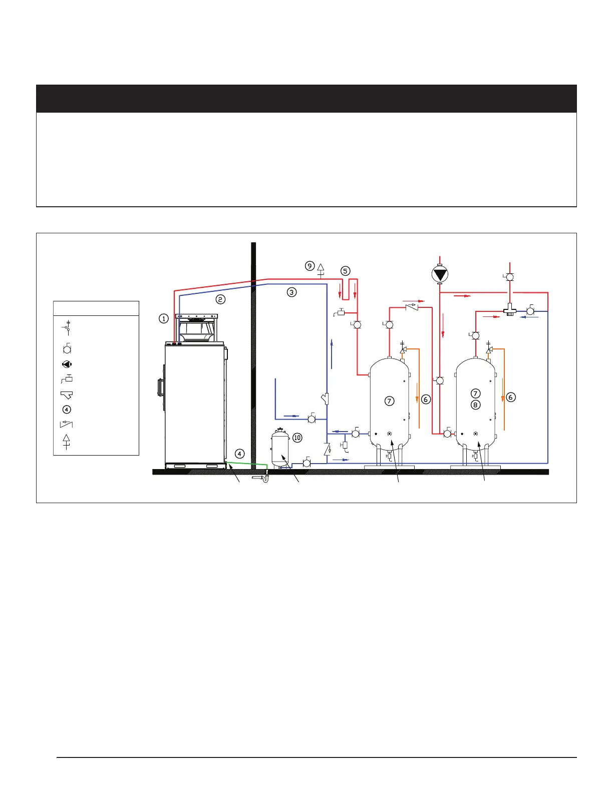
Typical Water Side Piping
An example of typical water side piping is shown in Figure 11 for reference. If piping extends below storage tank
drain points, install additional drain points at the lowest points on the piping.
CAUTION
Pipe Sizing and Care:
All connected piping must be sized for the design ow rates, appropriate velocity, and available head pressure for the heat pump
in use. Refer to the performance specications for this information. Ensure that pipes are clean and protected from intrusion of dirt
or other contaminants during the installation.
All connected pipes and components should be pressure tested with air before lling with water. A thorough ll and purge process is
required to remove any air bubbles from the lines BEFORE starting up the unit. Failure to purge piping of air bubbles can damage
the internal circulator. Install purge valves in the connected piping to facilitate this process.
Figure 11: Water Side Piping Concept
Outdoor Ambient
Conditions
Drain Point
Expansion Device
Primary Storage Swing Tank
Tempering
Station
Cold In
Recirc Return
Hot Water to Loads
e-Series
Heat Pump
Interior / Conditioned Space
Temperature and
Relief Valve
Ball Valve
Circulating Pump
Purge Valve
Wye Strainer
Installation Note
Check Valve
Legend
Air Vent
Piping Notes:
1. Exterior water piping and condensate piping require insulation in all cases. Heat Tracing is required on all pipes that could be exposed to freezing
conditions. UV jacketing is recommended for pipes exposed to sunlight. Insulate as per applicable energy codes, ambient conditions, and heat trace
requirements.
2. Pitch exterior run pipes down toward heat pump connections. This allows manual draining of exterior lines to the drain point within the heat pump.
Alternatively, sloping all pipes to the interior is permissible if slope is continuous to an interior drain point.
3. All piping between heat pump and storage should be sized for appropriate pressure drops and velocities. Refer to performance specications for
available pressure and ow rate requirements. Insulate interior piping as per applicable energy codes.
4. Condensate piping must be heat traced and insulated in all cases where piping could be exposed to freezing conditions. Pitch to freeze protected
drain point or to condensate pump.
5. Pump circulation between heat pump and storage tanks is required as a part of freeze protection in some conditions. No automatic devices that
interrupt ow may be installed between the heat pump and storage tank. Pipe a heat trap into the hot water line to stop unintended migration from
tanks to the heat pump.
6. Pipe pressure relief valve outlets to the oor, or as required by applicable codes and regulations.
7. Ensure storage and swing tanks are rated for potable usage, have adequate volume for the design, have required tappings at required locations,
and are approved to handle system ow rates without tting erosion.
8. Swing tank must have backup heat installed sufcient to cover at least the recirc system heat losses. Backup heat can be installed in the tank itself,
or piped to it from an external heater.
9. Air venting is recommended on high point of the hot water supply piping from the water heater. Use only air vents suitable for open systems. Ensure
the air vent is installed in an interior, protected space.
10. Expansion devices must be located on the swing tank side of the primary storage to swing tank/distribution system check valves.