HeatWater.com | WaterService@nyle.com | (800) 777-6953 IM-e360-122023
26
IM-e360-122023 HeatWater.com | WaterService@nyle.com | (800) 777-6953
Control Wiring
e-Series heat pumps have several contact points for
eld wiring of external controls. More contacts can
become available with the installation of various eld
accessories, and details on those accessories are
shown in their respective installation instructions.
Nyle recommends running enough conductors to
use all available contacts if the installation site would
make wire retrots challenging, even if those contacts
are not intended for use during the initial installation.
This allows changes and reconguration to happen
seamlessly in the future. Additional conductors are
recommended to allow for wire breakage, and/or the
addition of future accessories.
Table 7 lists the available contacts on the base heat
pump, and their function. For advanced conguration
guidance, see “Conguration” on page 30 for relevant
accessories.
All control wiring should follow best practices, local
codes and regulations, and NEC/CSA guidelines.
Do not steal power from powered contacts for external
devices. Follow all ratings and wire types for the con-
tacts as described in Table 7.
Control Wiring Installation
1. Identify the smaller, control access conduit in the
top of the heat pump. Remove the shipping plug to
access the conduit.
2. Open the electrical enclosure box.
3. Run incoming control wire conduit(s) to the heat
pump termination tting. Leave sufcient exposed
wire to sh into the heat pump conduit.
4. Fish the incoming control wires through the conduit
until they enter the enclosure box with enough ex-
cess length to reach the appropriate terminals. Use
of a lead wire and/or string may facilitate this pro-
cess: this conduit does not have midpoint access.
5. Finish exterior conduit connection to the unit using
a weather tight connection method. Conduits ter-
minate in female thread. See Table 7.
6. Connect power wires to their terminals. All control
wire terminals are located in the upper left of the
electrical enclosure box.
7. Close the electrical enclosure box.
CAUTION
Contacts labeled “Dry” are intended to switch power from
external sources. DO NOT APPLY EXTERNAL POWER
to any contact that is not “Dry”. Equipment damage and
system failure can result from applying power to a pow-
ered contact. Follow all power specs for each contact.
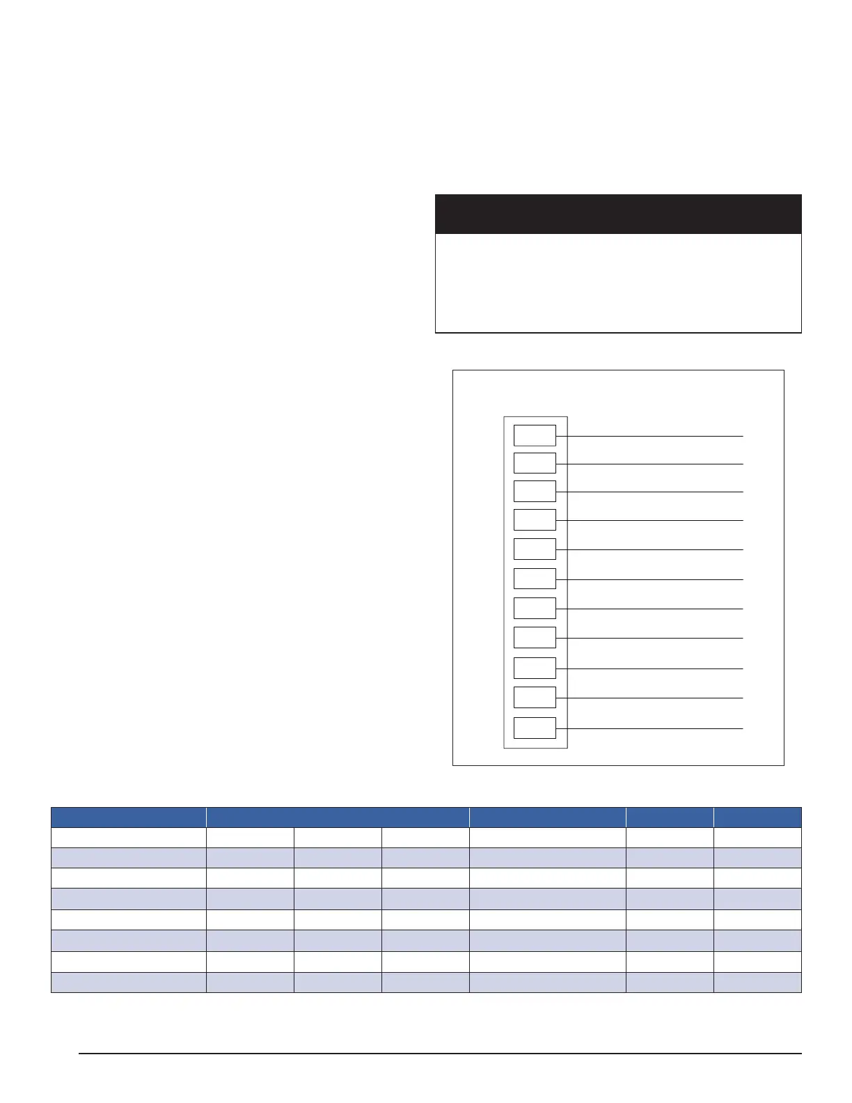
Diagram 4: Control Wiring Connections
Tank Sensor ON –
Tank Sensor ON +
BACnet MSTP SG
BACnet MSTP +
BACnet MSTP –
Alarm
Alarm
Run Signal
Run Signal
Remote Enable –
Remote Enable +
CTB
Control Terminal Block
CT11
CT10
CT9
CT8
CT7
CT6
CT5
CT4
CT3
CT2
CT1
Table 7: Control Wiring Connections
Contact Terminals Wire Type Power Rating
Remote Enable
CT1 CT2 -- Any 24Vdc --
Run Signal
CT3 CT4 -- Any Dry 4A/24V
Alarm Status
CT5 CT6 -- Any Dry 4A/24V
Reserved BMS
2
CT7 CT8 CT9 Stranded/Shielded Variable --
Tank Sensor 1
CT10 CT11w -- Stranded/Shielded -- 10k
Reserved OAS
2
CT12 CT13 -- Stranded/Shielded -- 10k
Service Mode
1
24V i7 -- Any 24Vdc 10k
Ethernet
See Note 3 -- -- CAT-5 or CAT-6 -- --
1
Service Mode enables access to Diagnose and Congure screens. Jump terminals for access.
2
Reserved terminals used by optional accessories and/or internal wiring. See accessory instructions.
3
Ethernet Port on Internal PLC controller.