HeatWater.com | WaterService@nyle.com | (800) 777-6953 IM-e360-122023
18
IM-e360-122023 HeatWater.com | WaterService@nyle.com | (800) 777-6953
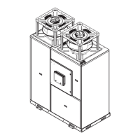
Figure 9: Fan Mounting Details
6X 3/8" Nylon Locknut
6X
3/8" Hex Bolt
8X 3/8" Hex Bolt
8X Sealing Washer
4X 3/8" Serrated Locknut
Wire Whip Entry
TOP VIEW
Wire Whip Entry
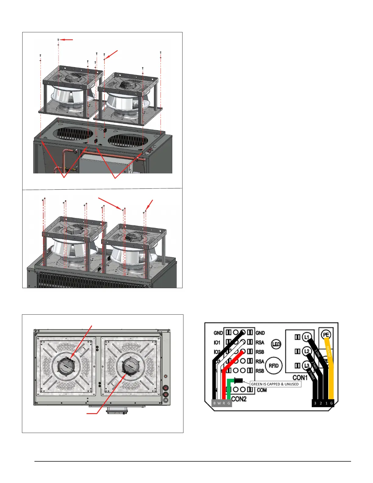
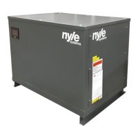
Figure 10: Fan Wire Locations
8X 3/8" Hex Bolt
8X Sealing Washer
4X 3/8" Serrated Locknut
Wire Whip Entry
TOP VIEW
Wire Whip Entry
Fan Wiring
1. Double check that the fans match the voltage of
the unit (either 230V or 460V), before connecting
the power feeds.
2. Open the top front access panel on the heat pump
by opening the electrical enclosure, and then re-
moving the internal screws holding the front ac-
cess panel in place.
3. In the top front compartment, identify the 4 bundles
of fan wires: 2 sets of fan power wires, and 2 sets
of fan control wires.
4. After the fans are mounted, locate the electrical en-
closure box on each fan, which has three cable t-
tings with caps. Open the enclosures by loosening
the screws in their lids.
5. Remove the caps from the appropriate cable ttings.
6. Locate the cable tting seals shipped inside the fan
enclosures.
7. Install cable tting seal on the uncapped cable ttings.
8. Feed fan power wires from heat pump through ca-
ble tting, 1 set to each fan.
9. Feed fan control wires from heat pump through ca-
ble tting, 1 set to each fan.
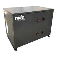
10. Starting with the ground wire, connect the power
wires to PE, L1, L2, and L3 terminals within the
enclosures of each fan.
11. Connect control wires to the control terminals in
each enclosure.
12. Tighten the cable ttings on the fans and on the
heat pump.
13. Close the fan enclosures.
Diagram 1: Fan Wiring Connections