HeatWater.com | WaterService@nyle.com | (800) 777-6953 IM-e360-122023 IM-e360-122023 HeatWater.com | WaterService@nyle.com | (800) 777-6953
23
Power Wiring
WARNING
Improper handling of unit electrical power can result in im-
mediate equipment damage, res, injury, and death. Ensure
only qualied personnel interact with main power lines. Nev-
er work while power is live; use all possible safety precau-
tions and perform all work in accordance with appropriate
local codes, National Electric Code, and/or CSA regulations.
Heat pump water heaters are voltage-specic, and re-
quire proper planning to provide the electrical support
appropriate to each unit. Refer to the electrical speci-
cations, specic product submittals, project documen-
tation, and the requirements and the following instal-
lation instructions.
e-Series units expect to have two separate power
feeds from the building: a main power feed, and a
smaller 120V power feed intended to be connected to
an electrical source with generator backup for freeze
protection during power outages.
If the unit will not be installed in freezing conditions,
and/or if the main power feed is itself on a generator,
an optional Unied Power Package accessory can be
ordered for 460V or 230V main power to consolidate
the two power feeds into a single point feed from the
building. It is very important that power outages and
freeze protection be considered in the power plan.
Unied Power Package instructions and wiring are in-
cluded in that accessory’s documentation.
208V main power feeds can be wired to provide uni-
ed power without a separate accessory. This requires
an additional neutral conductor and minor additional
wiring in the unit. See the following instructions and
Diagram 3 on page 25.
Power Requirements
1. Voltage is correct to within +/- 5% of ratings and
within +/-2% between phases.
2. Power is clean, reliable, and well grounded.
3. Wire and breakers are appropriately sized for the load.
4. Wire and breakers are properly specied for the en-
vironment they are installed in.
5. Backup generators should include line conditioning
suitable for running electronics.
6. Follow manufacturer’s torque specications for all
power wire equipment by others.
7. Install service disconnects on incoming power feeds
at the heat pump location.
8. All power wiring to the unit must be rated for 600V.
The e-Series heat pump has an incoming power feed
conduit from the interior electrical enclosure to a termi-
nation point on the top of the unit. This conduit ships with
a termination plug that will need to be removed to access
the conduit. Main and 120V power feeds will run through
the same conduit. A second, smaller conduit is used for
control wires. See Figure 13.
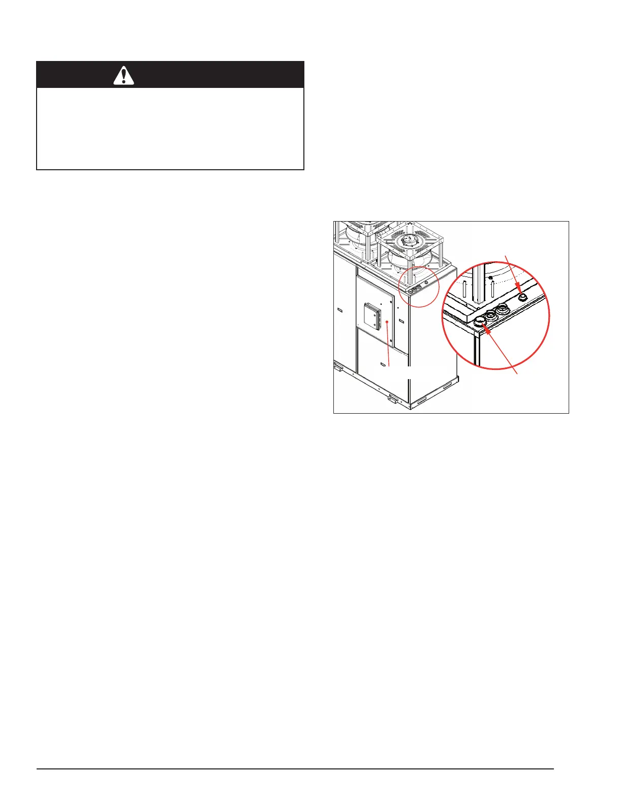
To Install the Power Wires
1. Identify the power entry conduit in the top of the heat
pump (Figure 13). Remove the shipping plug to ac-
cess the conduit.
Figure 13: Conduit Power Entry Locations
Power Entry Conduit
Control Entry Conduit
Electrical Enclosure
2. Open the electrical enclosure box
3. Run incoming power conduit(s) to the heat pump
termination tting. Leave sufcient exposed wire to
sh into the heat pump conduit. Be sure the wire is
sized for the load, or as dictated by local codes and
conditions, whichever is larger.
4. Route the incoming power wires through the conduit
into the enclosure box providing excess length to
reach the appropriate terminals. This conduit includes
a midpoint access to facilitate wiring installation.
5. Finish exterior conduit connection to the unit using
a weather tight connection method. Conduits termi-
nate in female thread.
6. Connect power wires to their terminals. Refer to ”Di-
agram 2: Power Wiring Connections” on page 24
Use 375 foot-pounds of torque on the heat pump’s
connection terminals. All power distribution terminals
are located in the upper right corner of the electrical
enclosure.
7. Close the electrical enclosure box.