Instruction Manual PCD 650
2
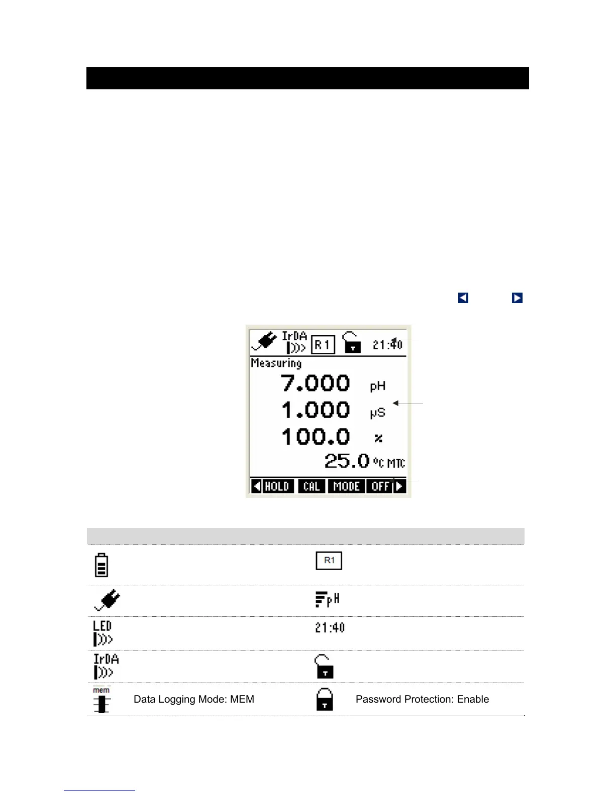
1.2 Display & Keypad
1.2.1 Display Overview
The large monochrome display shows detailed information about measurements,
various indicators, annunciators, functions and useful tips. The display consists of
3 main sections when the meter is in the measurement mode:
Header – Displays indicators for power source, battery level, pH probe
condition, conductivity range of the probe, data transmission mode, real-time
clock, user lock/unlock etc.
Body – Displays measurement related information.
Footer – Displays functions available for a given mode of operation. At any
given time, up to four function names are displayed, that correspond to 4
function keys in the keypad. Left & Right arrow icons are displayed when there
are more functions available than the 4-functions shown in the display. To
access a function, press the corresponding function key (in keypad) just below
the function name. To see other available functions, press left or right
arrow key in the keypad.
Figure 1: Display
Indicators Used in Header Area
Power Source & Battery Level:
Battery, level 80%-90%
Conductivity range of the probe
Power Source: DC Adapter
Average slope of the pH probe
Data Transmission mode: LED
Current Time in 24 Hour format
Data Transmission mode: Infrared
Password Protection: Disable
Data Logging Mode: MEM
Password Protection: Enable
Heade