Instruction Manual PCD 650
28
2.9 Salinity Measurement Mode
In Salinity measurement mode, the meter displays salinity and temperature reading.
2.9.1 Indicators in salinity measurement mode
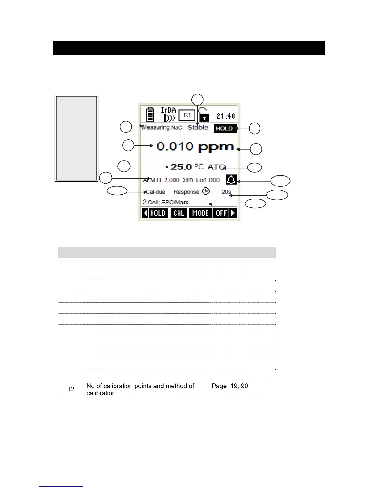
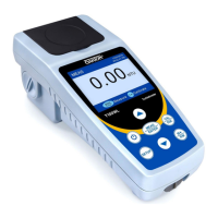
Figure 27 : Salinity measurement screen
Refer item numbers indicated in Figure 27.
Item Description More Details On
1 Measurement mode indicator -
2 Appears when the reading is stable Page 75
3 Appears when the reading is on hold Page 17, 75
4 Salinity reading -
5 Units of measurement -
6 Temperature reading & units Page 98
7 Temperature compensation mode Page 18, 98
8 Salinity HI & LO Alarm limits Page 90
9 Salinity Alarm indicator Page 18, 90
10 Response time Page 48
11 Calibration Due indicator Page 18, 90
12
No of calibration points and method of
calibration
Page 19, 90
1
4
5
6
7
3
2
9
8