9600 Periodic Maintenance Procedure 00-880606-02
Page 27
3.2 FLUORO RESOLUTION
FLUORO RESOLUTION
1. Install the Image Resolution Tool at a 45° angle to the image intensifier grid.
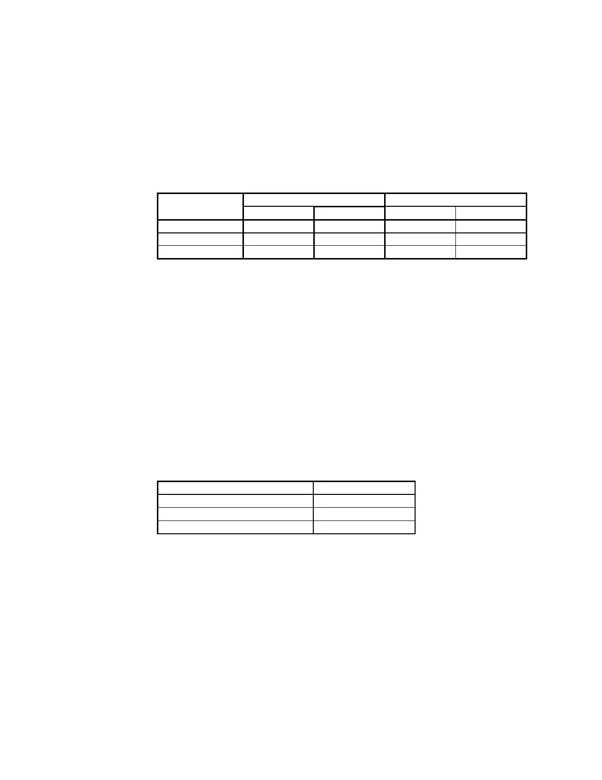
2. Press the X-ray ON switch and verify that the image resolution meets the following line
pairs/millimeter in each field size.
FIELD SIZE
9-inch Image Intensifier 12-inch Image Intensifier
60 Hz lp/mm
50 Hz lp/mm 60 Hz lp/mm 50 Hz lp/mm
NORMAL 1.4 lp/mm
1.2 lp/mm 1.0 lp/mm 1.0 lp/mm
MAG1 2.0 lp/mm
1.7 lp/mm 1.3 lp/mm 1.4 lp/mm
MAG2 2.4 lp/mm
2.0 lp/mm 1.6 lp/mm 2.0 lp/mm
3. Record the line pairs/millimeter for each field size on the PM Inspection Report form.
3.3 FLUORO PENETRATION TEST
KV TRACKING NORMAL AUTO MODE
1. Select the STANDARD ABS Table.
2. Select AUTO FLUORO technique mode and the NORMAL field size.
3. Make exposures with one, two, and three copper filters added in the beam path and verify that the
kVp tracks as indicated in the following list. Record the resulting kVp and mA values on the PM
form.
NUMBER OF FILTERS kVp Range
one 60 ± 3 kVp
two 70 ± 3 kVp
three 78 ± 3 kVp
4. PREVENTATIVE MAINTENANCE ACTIONS
AIR FILTERS CLEANED, 9600 COOLING KIT
This procedure is applicable only if the system (Std. C-Arm or Super C-Arm) is equipped with the 9600
Cooling Kit, which includes the ventilated HV cable cover and air vent filters.
1. Switch OFF the Workstation keyswitch (if not already switched off), then remove the HV cable
cover from the X-ray tube (if not already removed). You may want to disconnect the fan wires for
easier access to the inside of the cover.