Basic Operations > 9
B
ASIC
O
PERATIONS
M
AIN
C
OMPONENTS
AND
T
HEIR
F
UNCTIONS
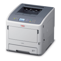
S
TANDARD
C
ONFIGURATION
NO. NAME DESCRIPTION
1. Centre output
tray
Print jobs are output here with the printed side
facing down.
2. Control panel Consists of the essential operation buttons,
indicators and display.
3. Ventilation
hole
Releases heat to prevent the interior of the
printer from heating up. Do not block.
4. Paper meter A meter to check the amount of remaining
paper. Attached to the 550 tray.
5. Tray 1 Sets the 150 tray.
6. Tray 2 Sets the 550 tray.
7. Power switch Switches the power of the printer on and off.
Pressing the switch to the <|> position switches
it on and pressing it to the <0> position
switches it off.
8. Paper
extension
Raise this when printing on paper larger than
Letter/A4 size.
9. Host USB port For connecting the USB Flash Drive.
10. Power cord
cable
connector
For connecting the power cord cable.
11. Parallel
connector
For connecting the parallel cable.
12. Network
connector
For connecting the network cable when
connecting this printer to the network for use.
13. USB connector For connecting the USB cable.
10
11
12
13
14
15
3
3
3
12
3
4567
8
9