44292401TH Rev.1
125 /
Oki Data CONFIDENTIAL
ADJUSTMENT/SETTING
Function
• To adjust for variations in the accuracy of IR parts and their mounting accuracy by
varying the scanning zoom ratio in the sub-scanning direction.
Use
• When the MFP board has been replaced.
• When the Scanner unit has been replaced
NOTE
• When the MFP board is replaced, the setting value is cleared. Re-entering a new
setting value is necessary.
Adjustment
Specification
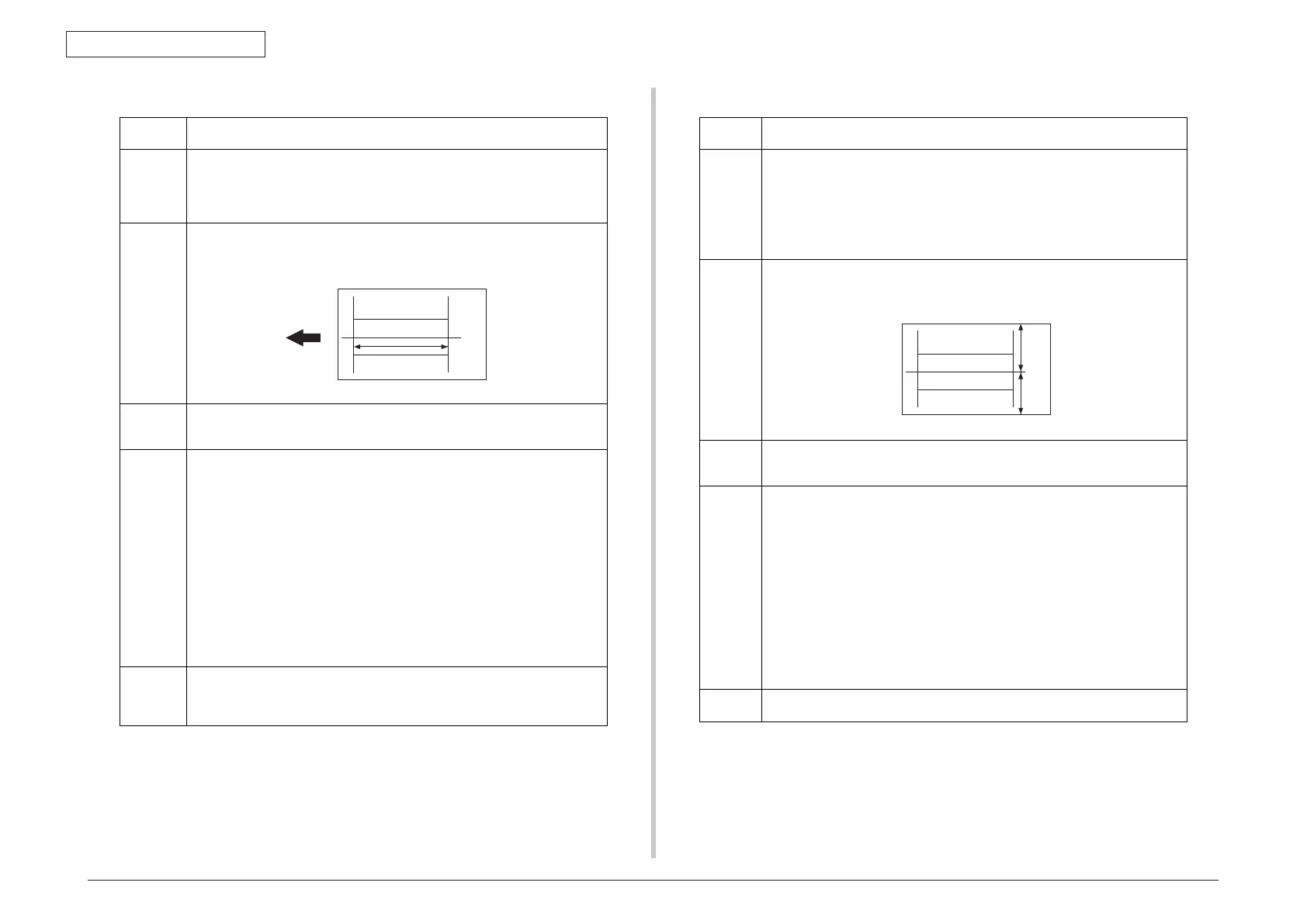
• Adjust the width of E in the copy of the test pattern1 so that the following specification
is met.
• 200 ± 0.5% (Zoom Ratio = Full Size:100%)
Adjustment
Range
• The default setting is 0%.
• -2.0% ~ “0%” ~ +2.0%
• Step: 0.2%
Setting/
Procedure
1. Print the test pattern1.
See P.131
2. Enter the [ADJUST] menu in the service mode.
3. Select [CIS SUB ZOOM] of [ADJUST] and press the Select key.
4. Place the test pattern1 on the Original Glass and make a test copy.
NOTE
• The test pattern1 should be positioned vertically.
• Use A4 or Letter paper loaded into tray1 to make the test copy.
5. Check that the width of E in the copy of the test pattern1 meets the specification.
Calculation: (1 - Width of E in the document y Width of E in the copy) u 100
If the width of E is out of specification, adjust it according to the following procedure.
6. Press the Select key.
7. Using the S/T key, change the setting value and then press the Select key.
8. Place the test pattern1 on the Original Glass. Then, make a test copy again and check
it.
Adjustment
Instructions
• If the width of E in the test pattern is longer than the specified width
..... Decrease the setting.
• If the width of E in the test pattern is shorter than the specified width
..... Increase the setting.
4139F3C549DA
E
Function
• To adjust for variations in the accuracy of IR parts and their mounting accuracy by vary-
ing the scanning start position in the main scanning direction.
Use
• When the MFP board has been replaced.
• When the original glass is replaced.
• When the Scanner unit has been replaced
NOTE
• When the MFP board is replaced, the setting value is cleared. Re-entering a new
setting value is necessary.
• After the [CIS MAIN ZOOM] adjustments have been performed
Adjustment
Specifica-
tion
• Adjust the amount that widths A and B in the copy of the test pattern1 so that the follow-
ing specification is met.
• 0 ± 2.0 mm
Adjustment
Range
• The default setting is 0.
• -5.0 (-5.0 mm) ~ “0.0 (0.0 mm)” ~ +5.0 (+5.0 mm)
• Step: 0.5 mm
Setting/
Procedure
1. Print the test pattern1.
See P.131
2. Enter the [ADJUST] menu in the service mode.
3. Select [CIS MAIN REGIST] of [ADJUST] and press the Select key.
4. Place the test pattern1 on the Original Glass and make a test copy.
NOTE
• The test pattern1 should be positioned vertically.
• Use A4 or Letter paper loaded into tray1 to make the test copy.
5. Check the amount that widths A and B in the copy of the test pattern are shifted.
If the shift is out of specification, adjust it according to the following procedure.
6. Press the Select key.
7. Using the S/T key, change the setting value and then press the Select key.
8. Place the test pattern1 on the Original Glass. Then, make a test copy again and check
it.
Adjustment
Instructions
• If the width of A is less than the width of B..... Increase the setting.
• If the width of B is less than the width of A..... Decrease the setting.
4139F3C546DA
A
B
13.4.3 CIS MAIN REGIST13.4.2 CIS SUB ZOOM
 Loading...