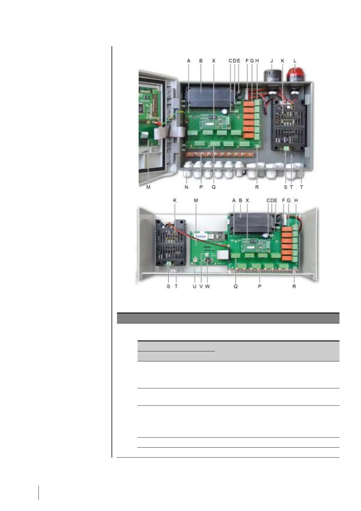
Internal view
Figure 9: Internal view of the wall-mounted version (top) and rack- mounted version
(bottom).
LED digital communication status indicators. The information displayed by each red-green
diode pair of a line is interpreted as follows:
Normal functioning of the line
- Tx communication request
- Rx: response of digital module(s).
Bad communication quality with at least one module.
Communication failure. Absence or failure of line
modules. A communication failure is signaled by the
activation of the internal buzzer, the presence of the
orange failure indicator and via the default relay.
No digital module active on the line.
Optional 24 VDX NiMH battery pack.