C –Logic input connectors
Each of these 16 inputs can be connected to a voltage-free contact as per
Figure 39. Input status is transmitted by the digital line to the MX 43. There is
no alarm when the contact is closed.
Connection
Refer to Chapter 6, on page 33.
Configuration
Configured via the COM 43 application.
8-Analog Input Module
Function
This digital module enables the
monitoring of 8 analog (4-20 mA or
Wheatstone bridge) inputs.
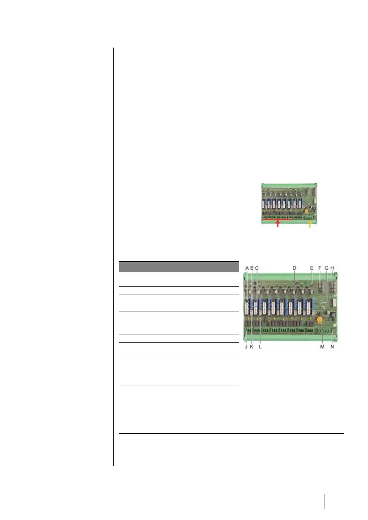
Figure 23: 8-analog inputs.
Introduction
Figure 24: Module of 8-analog inputs.
Jumper of configuration 4-20mA or a
Wheatstone bridge.
Measuring point of each line.
Reference 1.2 V for bridge calibration.
Start/stop input switches not used,
always in ON position.
Lug 0V for 4-20mA calibration.
PCB configuration switches (digital
address, delay).
Inputs no.1 to 8 (4-20mA or Wheatstone
bridge as per. A.
Filament current calibration (factory
setting).
4-20mA division strap in case of parallel
operation of several analog detectors on
the same line (application parking).
Power supply and digital network
connector.
End of line resistor jumper. (raised
position, EOL resistor connected).