Relay modules
Function
This digital module, available in two
versions, allows for the management
of:
■ 1 to 4 relay outputs;
■ Or 1 to 8 relays.
In addition, it has 2 logic inputs.
Figure 19: 8-relay module.
Introduction
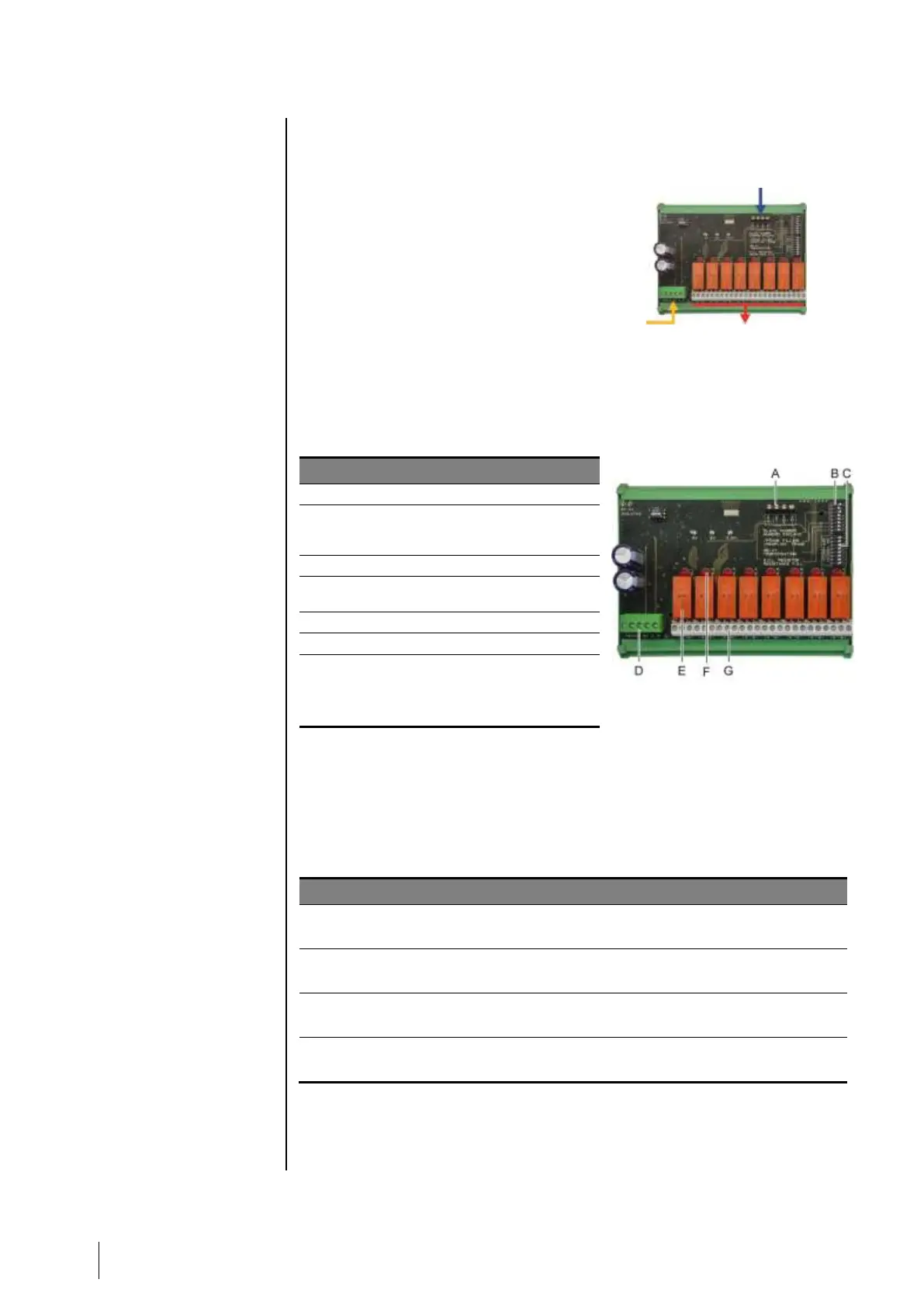
Figure 20: 8-relay module.
Connector for 2 logic inputs.
Configuration switches of the module
(digital address, delay, and end of line
resistor).
Switches for relay configuration.
Power supply and digital network
connector.
Programmable relay (4 or 8).
A – Logic input connectors
Each of these two terminals (Figure 20, A) may be connected to a voltage-free
contact as per Figure 38. There is no alarm when the contact is open.
B – Module configuration switches
These switches are set according to the following table.
Slave number
Numéro esclave
See details in the paragraph Module Address on page 24.
Frame filling
Remplissage de trame
Factory settings. Do not modify.
Factory settings. Do not modify.
E.O.L Resistor
Résistance F.D.L.
See details in paragraph End of line Resistor, on page 25.
Table 6: Relay module configuration switches.
4 or 8 output relays
(CRT 250 VAC – 2A)