4-Analog Output Module
Function
This digital module delivers 1 to 4
independent analog values (4-20 mA
outputs) opto-isolated from the values
given by the MX 43, capable of being
independently activated or deactivated:
■ Activated: The 4-20mA signal varies
depending on the input.
■ Deactivated: The 4-20mA signal is
blocked at 0 mA, whatever the input
signal.
Figure 25: Principle 4-analog output
module.
Several analog values may be associated to the same 4-20mA output
authorizing the management of minimums, maximums, or averages from a
group of detectors This module likewise has 2 logic inputs.
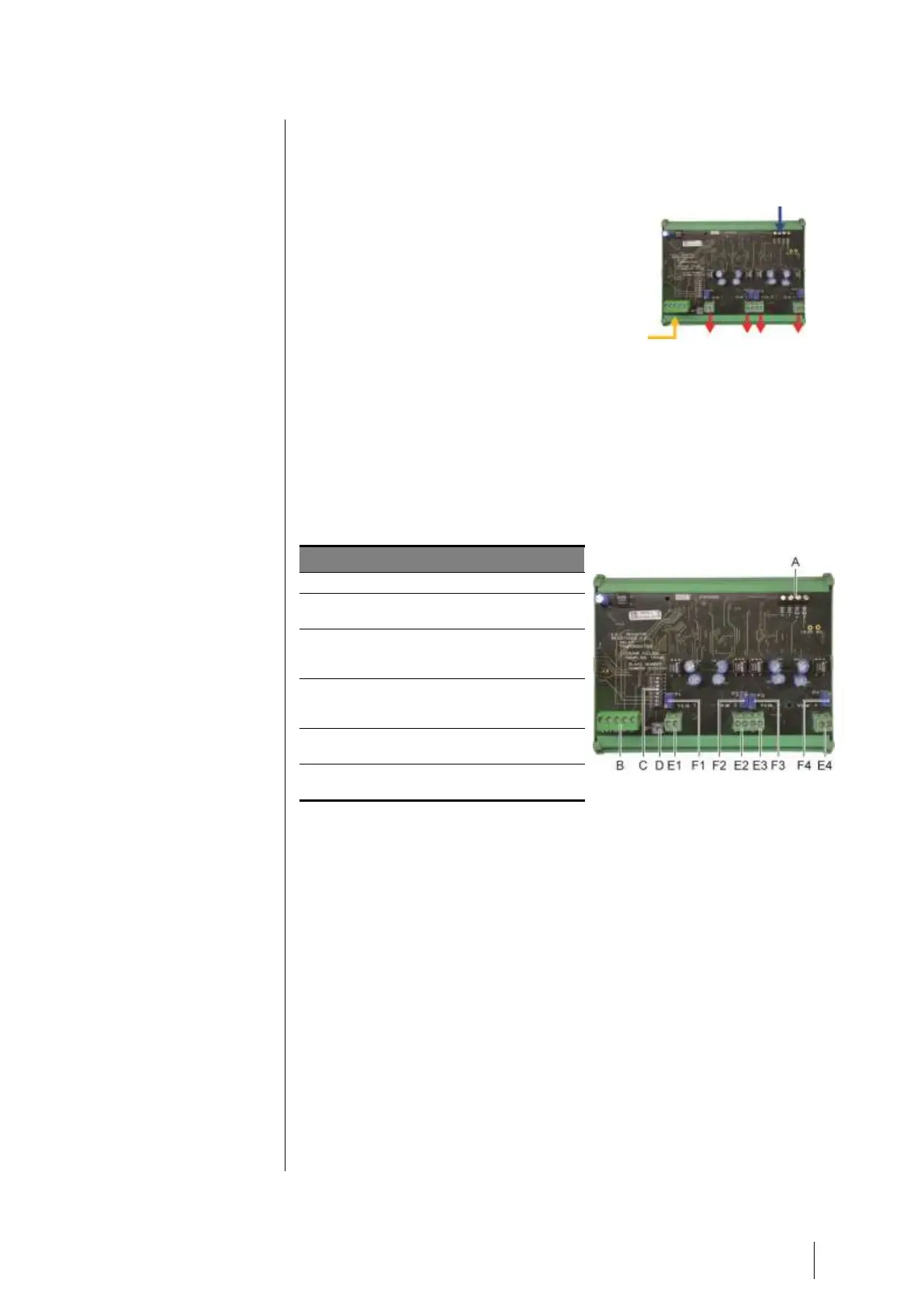
Introduction
Connector for 2 logic inputs.
Power supply and digital network
connector.
Module configuration switches (digital
address, delay, and end of line
resistor).
Push-button. Pressing this button
generates 20mA current in the output
of each line.
(E1 to E4) opto-isolated independent
4-20mA analog outputs.
(F1 to F4) 20mA calibration in line
output.
Figure 26: 4-analog output module.
A –Logic input connectors
Each of these two terminal jacks (Figure 26, A) may be connected to a
voltage-free contact in accordance with Figure 38. Input status is transmitted
by the digital line to the MX 43.
C – Module configuration switches
These switches are set according to the following table: